
Machine Elements in Mechanical Design (6th Edition) (What's New in Trades & Technology)
6th Edition
ISBN: 9780134441184
Author: Robert L. Mott, Edward M. Vavrek, Jyhwen Wang
Publisher: PEARSON
expand_more
expand_more
format_list_bulleted
Concept explainers
Videos
Textbook Question
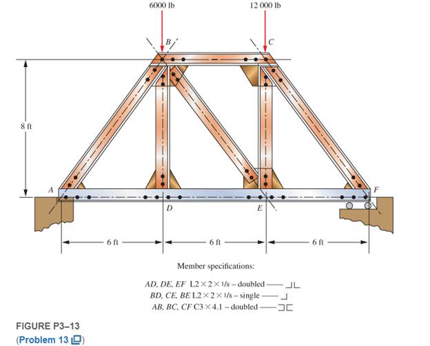
Chapter 3, Problem 13P
The truss shown in Figure P3−13 spans a total space of 18.0 ft and carries two concentrated loads on its top chord. The members are made from standard steel angle and channel shapes as indicated in the figure. Consider all joints to be pinned. Compute the stresses in all members near their midpoints away from the connections.
Expert Solution & Answer
Want to see the full answer?
Check out a sample textbook solution
Students have asked these similar questions
Quiz/An eccentrically loaded bracket is welded to the support as shown in Figure below. The load is static. The weld size
for weld w1 is h1 = 6mm, for w2 h2 = 5mm, and for w3 is h3 =5.5 mm. Determine the safety factor (S.f) for the welds.
F=22 kN. Use an AWS Electrode type (E90xx).
I want university professor
solutions
O REDMI NOTE 8 PRO
CAI QUAD CAMERA
140
S
101.15
F
Research and select different values for the R ratio from various engine models, then analyze how these changes affect instantaneous velocity and acceleration, presenting your findings visually using graphs
Meh
Battery operated train
Coll CD Af Pair
160,000kg 0.0005 0.15 5m² 1.2kg/m³
19
7et nong
0.98 0.9 0.88
Tesla Prated
Tesla Trated Ywheel ng Jaxle.
270kW
440NM
0.45m 20
2
8.5kgm²
Consider a drive cycle of a 500km trip with 3 stops in
the middle. Other than the acceleration and deceleration
associated with the three stops, the tran maintains.
constant cruise speed velocity of 324 km/hr. The
tran will fast charge at each stop for 15 min at a
rate Peharge = 350 kW
(ผม
τ
(MN
15MIN
Stop
w charging
(350kW
GMIJ
restored during 15
minutes of fast charging at
Calculate the battery energy Pcharge = 350kW
Calculate the net energy gain per stop
t
64
Determice the total battery energy required Ebat
to complete the 500km trip with 3 stops.
etc
Chapter 3 Solutions
Machine Elements in Mechanical Design (6th Edition) (What's New in Trades & Technology)
Ch. 3 - A tensile member in a machine structure is...Ch. 3 - Compute the stress in a round bar having a...Ch. 3 - Compute the stress in a rectangular bar having...Ch. 3 - A link in a packaging machine mechanism has a...Ch. 3 - Two circular rods support the 3800 lb weight of a...Ch. 3 - A tensile load of 5.00 kN is applied to a square...Ch. 3 - An aluminum rod is made in the form of a hollow...Ch. 3 - Compute the stress in the middle portion of rod AC...Ch. 3 - Compute the forces in the two angled rods in...Ch. 3 - If the rods from Problem 9 are circular, determine...
Ch. 3 - Repeat Problems 9 and 10 if the angle is 15 .Ch. 3 - Figure P312 shows a small truss spanning between...Ch. 3 - The truss shown in Figure P313 spans a total space...Ch. 3 - Figure P314 shows a short leg for a machine that...Ch. 3 - Consider the short compression member shown in...Ch. 3 - Refer Figure P38 . Each of the pins at A, B, and C...Ch. 3 - Compute the shear stress in the pins connecting...Ch. 3 - Prob. 18PCh. 3 - Prob. 19PCh. 3 - Prob. 20PCh. 3 - Prob. 21PCh. 3 - Compute the torsional shear stress in a circular...Ch. 3 - If the shaft of Problem 22 is 850 mm long and is...Ch. 3 - Compute the torsional shear stress due to a torque...Ch. 3 - Compute the torsional shear stress in a solid...Ch. 3 - Compute the torsional shear stress in a hollow...Ch. 3 - Compute the angle of twist for the hollow shaft of...Ch. 3 - A square steel bar, 25 mm on a side and 650 mm...Ch. 3 - A 3.00 in-diameter steel bar has a flat milled on...Ch. 3 - A commercial steel supplier lists rectangular...Ch. 3 - A beam is simply supported and carries the load...Ch. 3 - For each beam of Problem 31, compute its weight if...Ch. 3 - For each beam of Problem 31, compute the maximum...Ch. 3 - For the beam loading of Figure P334, draw the...Ch. 3 - For the beam loading of Figure P334, design the...Ch. 3 - Figure P336 shows a beam made from 4 in schedule...Ch. 3 - Select an aluminum I-beam shape to carry the load...Ch. 3 - Figure P338 represents a wood joist for a...Ch. 3 - For Problems 39 through 50, draw the free-body...Ch. 3 - Prob. 40PCh. 3 - For Problems 39 through 50, draw the free-body...Ch. 3 - Prob. 42PCh. 3 - Prob. 43PCh. 3 - Prob. 44PCh. 3 - For Problems 39 through 50, draw the free-body...Ch. 3 - For Problems 39 through 50, draw the free-body...Ch. 3 - For Problems 39 through 50, draw the free-body...Ch. 3 - For Problems 4850, draw the free-body diagram of...Ch. 3 - For Problems 4850, draw the free-body diagram of...Ch. 3 - Prob. 50PCh. 3 - Compute the maximum tensile stress in the bracket...Ch. 3 - Compute the maximum tensile and compressive...Ch. 3 - For the lever shown in Figure P353 (a), compute...Ch. 3 - Compute the maximum tensile stress at sections A...Ch. 3 - Prob. 55PCh. 3 - Refer to Figure P38. Compute the maximum tensile...Ch. 3 - Prob. 57PCh. 3 - Refer to P342. Compute the maximum stress in the...Ch. 3 - Refer to P343. Compute the maximum stress in the...Ch. 3 - Prob. 60PCh. 3 - Figure P361 shows a valve stem from an engine...Ch. 3 - The conveyor fixture shown in Figure P362 carries...Ch. 3 - For the flat plate in tension in Figure P363,...Ch. 3 - For Problems 64 through 68, compute the maximum...Ch. 3 - For Problems 64 through 68, compute the maximum...Ch. 3 - For Problems 64 through 68, compute the maximum...Ch. 3 - For Problems 64 through 68, compute the maximum...Ch. 3 - Prob. 68PCh. 3 - Figure P369 shows a horizontal beam supported by a...Ch. 3 - Prob. 70PCh. 3 - Prob. 71PCh. 3 - The beam shown in Figure P372 is a stepped, flat...Ch. 3 - Figure P373 shows a stepped, flat bar having a...Ch. 3 - Figure P374 shows a bracket carrying opposing...Ch. 3 - Prob. 75PCh. 3 - Figure P376 shows a lever made from a rectangular...Ch. 3 - For the lever in P376, determine the maximum...Ch. 3 - Figure P378 shows a shaft that is loaded only in...Ch. 3 - Prob. 79PCh. 3 - Prob. 80PCh. 3 - A hanger is made from ASTM A36 structural steel...Ch. 3 - A coping saw frame shown in Figure P382 is made...Ch. 3 - Prob. 83PCh. 3 - Figure P384 shows a hand garden tool used to break...Ch. 3 - Figure P385 shows a basketball backboard and goal...Ch. 3 - Prob. 86P
Knowledge Booster


Learn more about
Need a deep-dive on the concept behind this application? Look no further. Learn more about this topic, mechanical-engineering and related others by exploring similar questions and additional content below.Similar questions
- DO NOT COPY SOLUTION The differential equation of a cruise control system is provided by the following equation: Find the closed loop transfer function with respect to the reference velocity (vr) . a. Find the poles of the closed loop transfer function for different values of K. How does the poles move as you change K? b. Find the step response for different values of K and plot in MATLAB. What can you observe? c. For the given transfer function, find tp, ts, tr, Mp . Plot the resulting step response. G(s) = 40/(s^2 + 4s + 40)arrow_forwardAswatan gas occupies a space of 0.3 millike cube at a pressure of 2 bar and temperature of 77 degree Celsius it is indicate at constant volume at pressure of 7 parts determine temperature at the end of process mass of a gas changing internal energy change in enthalpy during the process assume CP is equal to 10 1.005 CV is equal to 0.712 is equal to 287arrow_forwardAUTO CONTROLDNO COPIED ANSWERS, SHOW FULL SOLUTION The differential equation of a DC motor can be described by the following equation Find the transfer function between the applied voltage ( Va)and the motor speed (thetadot m). What is the steady state speed of the motor after a voltage (Va = 10V) has been applied. Find the transfer function between the applied voltage (Va) and the shaft angle (thetadot m) .arrow_forward
- Auto Controls DONT COPY ANSWERS Perform the partial fraction expansion of the following transfer function and find the impulse response: G(s) = (s/2 + 5/3) / (s^2 + 4s + 6) G(s) =( 6s^2 + 50) / (s+3)(s^2 +4)arrow_forwardDerive the Laplace transform of the following functions. Use the definition of Laplace transform. f(t)=sin4t and f(t)=cos2t Auto Controlsarrow_forwardhelparrow_forward
- any help i dont understandarrow_forwardBattery operated train Mueh Groll CD Af Pair 160,000 kg 0.0005 0.15 19 5m² 1.2kg/m³ 0.98 0.9 Tet neng 0.88 Tesla Prated Tesla Trated Ywheel ng Joyle 2 270 kW 440NM 0,45m 20 8.5kg m Consider a drive cycle of a 500km trip with 3 stops in the middle. Other than the acceleration and deceleration associated with the three stops, the tran maintains. constant cruise speed velocity of 324 km/hr. The tran will fast charge at each stop for 15 min at a rate Peharge = 350 kW Εμ (MN 15MIN Stop w charging (350kW) GMIJ t 6MM 6AW 1) calculate the battery power required to mantain. constant velocity of 324km/hr 2) determine the battery energy, energy required to constant velocity portion of this drive. Cover the 3) calculate the battery energy required to accelerate the train to 324/04/hr. 4) calculate the battery energy that is either fost in deceleration or recovered due to regenerative breaking etcarrow_forwardA 22-lb block B rests as shown on a 28-lb bracket A. The coefficients of friction are μs=0.30μs=0.30 and μk=0.25μk=0.25 between block B and bracket A, and there is no friction in the pulley or between the bracket and the horizontal surface. solved in a previous part. max weight of block C if block B is not to slide on bracket A is 5.045 lbs. Please solve for the acceleration of each Blockarrow_forward
- Test 1 .DOCX * A File Edit View Tools Help INDUSTRIAL ENGINEERING PROGRAMME IMB 411-INDUSTRIAL LOGISTICS TEST 1- SEPTEMBER 12, 2012 Instructions: Answer all questions. Time allowed is 1.5 hours. Identify your script with your student number ONLY (Do not write your name). 1. Define the following terms (i) Logistics management (ii) Supply chain management (iii) Vertical integration in a supply chain (3 Marks) (3 Marks) (3 Marks) 2. (a) Using examples of your choice, briefly discuss the following levels of customer service (1) Pre-transaction elements (ii) Transaction elements (4 Marks) (4 Marks) (iii) Post-transaction elements (4 Marks) (b) "The challenge facing Dumelang Enterprise (Pty) Ltd is to establish the real profitability of their customers and to develop service strategies that will improve the profitability of all customers". As a logistics consultant, briefly discuss how you can advise Dumelang's customer service management. 3. (a) List the three main forms of inventory in a…arrow_forwardIt is decided to install several single-jet Pelton wheels to produce a total power of 18 MW. The available head is 246 m. The wheel rotational speed is 650 rpm and the speed ratio (❤) = 0.46. The diameter of the nozzle (jet) is limited to be 0.167 m with a Cv of 0.95. The efficiency of each turbine is 87%. Determine: (1) The number of Pelton wheels to be used, and (2) The bucket angle.arrow_forwardPlease show All work and fill it in thermodynamicsarrow_forward
arrow_back_ios
SEE MORE QUESTIONS
arrow_forward_ios
Recommended textbooks for you
 Mechanics of Materials (MindTap Course List)Mechanical EngineeringISBN:9781337093347Author:Barry J. Goodno, James M. GerePublisher:Cengage Learning
Mechanics of Materials (MindTap Course List)
Mechanical Engineering
ISBN:9781337093347
Author:Barry J. Goodno, James M. Gere
Publisher:Cengage Learning
Everything About COMBINED LOADING in 10 Minutes! Mechanics of Materials; Author: Less Boring Lectures;https://www.youtube.com/watch?v=N-PlI900hSg;License: Standard youtube license