
Machine Elements in Mechanical Design (6th Edition) (What's New in Trades & Technology)
6th Edition
ISBN: 9780134441184
Author: Robert L. Mott, Edward M. Vavrek, Jyhwen Wang
Publisher: PEARSON
expand_more
expand_more
format_list_bulleted
Concept explainers
Videos
Textbook Question
Chapter 3, Problem 84P
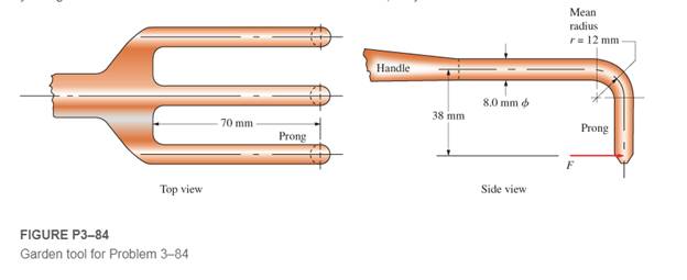
Figure P3−84 shows a hand garden tool used to break up soil. Compute the force applied to the end of one prong that would cause yielding in the curved area. The tool is made from cast aluminum, alloy 356.0-T6.
Expert Solution & Answer
Want to see the full answer?
Check out a sample textbook solution
Students have asked these similar questions
a problem existed at the stocking stations of a mini-load AS/RS (automated storage and retrieval system) of a leading electronics manufacturer (Fig.1). At these stations, operators fill the bin delivered by the crane with material arriving in a tote over a roller conveyor. The conveyor was designed at such a height that it was impossible to reach the hooks comfortably even with the tote extended. Furthermore, cost consideration came into the picture and the conveyor height was not reduced. Instead, a step stool was considered to enable the stocker to reach the moving hooks comfortably. The height of the hooks from the floor is 280.2 cm (AD). The tote length is 54.9 cm. The projection of tote length and arm reach, CB = 66.1 cm. a) What anthropometric design principles would you follow to respectively calculate height, length, and width of the step to make it usable to a large number of people? b) What is the minimum height (EF) of the step with no shoe allowance? c) What is the minimum…
Qu. 5 Composite materials are becoming more widely used in aircraft industry due to their high strength, low weight and excellent corrosion resistant properties. As an engineer who is given task to design the I beam section of an aircraft (see Figure 7) please, answer the following questions given the material properties in Table 3.
Determine the Moduli of Elasticity of Carbon/Epoxy, Aramid/Epoxy, and Boron /Epoxy composites in the longitudinal direction, given that the composites consist of 25 vol% epoxy and 75 vol% fiber.
What are the specific moduli of each of these composites?
What are the specific strengths (i.e. specific UTS) of each of these composites?
What is the final cost of each of these composites?please show all work step by step problems make sure to see formula material science
Mueh
Battery operated train
Coll
160,000kg 0.0005 0.15 5m² 1.2kg/m³
CD
Af Pair
19
пре neng
0.98 0.9
0.88
Tesla Prated
Tesla Trated "wheel ng
Joxle
270 kW
440NM
0,45m 20
8.5kg m2
the middle
Consider a drive cycle of a 500km trip with 3 stops in
Other than the acceleration and deceleration
associated with the three stops, the tran maintains
constat cruise speed velocity of 324 km/hr. The
tran will fast charge at each stop for 15 min at a
rate Peharge = 350 kW
ΟΙ
15MIN
Stop
w charging
(350kW)
(ผม
τ
(AN
GMIJ
t
6M
1) HOW MUCH DISTANCE dace is covered DURING THE
ACCELERATION TO 324 km/hr?
2)
DETERMINE HOW LONG (IN seconds) the tran will
BE TRAVELING AT FULL SPEED
2
?
3) CALCULATE THE NET ENERGY GAW PER STOP
ete
Chapter 3 Solutions
Machine Elements in Mechanical Design (6th Edition) (What's New in Trades & Technology)
Ch. 3 - A tensile member in a machine structure is...Ch. 3 - Compute the stress in a round bar having a...Ch. 3 - Compute the stress in a rectangular bar having...Ch. 3 - A link in a packaging machine mechanism has a...Ch. 3 - Two circular rods support the 3800 lb weight of a...Ch. 3 - A tensile load of 5.00 kN is applied to a square...Ch. 3 - An aluminum rod is made in the form of a hollow...Ch. 3 - Compute the stress in the middle portion of rod AC...Ch. 3 - Compute the forces in the two angled rods in...Ch. 3 - If the rods from Problem 9 are circular, determine...
Ch. 3 - Repeat Problems 9 and 10 if the angle is 15 .Ch. 3 - Figure P312 shows a small truss spanning between...Ch. 3 - The truss shown in Figure P313 spans a total space...Ch. 3 - Figure P314 shows a short leg for a machine that...Ch. 3 - Consider the short compression member shown in...Ch. 3 - Refer Figure P38 . Each of the pins at A, B, and C...Ch. 3 - Compute the shear stress in the pins connecting...Ch. 3 - Prob. 18PCh. 3 - Prob. 19PCh. 3 - Prob. 20PCh. 3 - Prob. 21PCh. 3 - Compute the torsional shear stress in a circular...Ch. 3 - If the shaft of Problem 22 is 850 mm long and is...Ch. 3 - Compute the torsional shear stress due to a torque...Ch. 3 - Compute the torsional shear stress in a solid...Ch. 3 - Compute the torsional shear stress in a hollow...Ch. 3 - Compute the angle of twist for the hollow shaft of...Ch. 3 - A square steel bar, 25 mm on a side and 650 mm...Ch. 3 - A 3.00 in-diameter steel bar has a flat milled on...Ch. 3 - A commercial steel supplier lists rectangular...Ch. 3 - A beam is simply supported and carries the load...Ch. 3 - For each beam of Problem 31, compute its weight if...Ch. 3 - For each beam of Problem 31, compute the maximum...Ch. 3 - For the beam loading of Figure P334, draw the...Ch. 3 - For the beam loading of Figure P334, design the...Ch. 3 - Figure P336 shows a beam made from 4 in schedule...Ch. 3 - Select an aluminum I-beam shape to carry the load...Ch. 3 - Figure P338 represents a wood joist for a...Ch. 3 - For Problems 39 through 50, draw the free-body...Ch. 3 - Prob. 40PCh. 3 - For Problems 39 through 50, draw the free-body...Ch. 3 - Prob. 42PCh. 3 - Prob. 43PCh. 3 - Prob. 44PCh. 3 - For Problems 39 through 50, draw the free-body...Ch. 3 - For Problems 39 through 50, draw the free-body...Ch. 3 - For Problems 39 through 50, draw the free-body...Ch. 3 - For Problems 4850, draw the free-body diagram of...Ch. 3 - For Problems 4850, draw the free-body diagram of...Ch. 3 - Prob. 50PCh. 3 - Compute the maximum tensile stress in the bracket...Ch. 3 - Compute the maximum tensile and compressive...Ch. 3 - For the lever shown in Figure P353 (a), compute...Ch. 3 - Compute the maximum tensile stress at sections A...Ch. 3 - Prob. 55PCh. 3 - Refer to Figure P38. Compute the maximum tensile...Ch. 3 - Prob. 57PCh. 3 - Refer to P342. Compute the maximum stress in the...Ch. 3 - Refer to P343. Compute the maximum stress in the...Ch. 3 - Prob. 60PCh. 3 - Figure P361 shows a valve stem from an engine...Ch. 3 - The conveyor fixture shown in Figure P362 carries...Ch. 3 - For the flat plate in tension in Figure P363,...Ch. 3 - For Problems 64 through 68, compute the maximum...Ch. 3 - For Problems 64 through 68, compute the maximum...Ch. 3 - For Problems 64 through 68, compute the maximum...Ch. 3 - For Problems 64 through 68, compute the maximum...Ch. 3 - Prob. 68PCh. 3 - Figure P369 shows a horizontal beam supported by a...Ch. 3 - Prob. 70PCh. 3 - Prob. 71PCh. 3 - The beam shown in Figure P372 is a stepped, flat...Ch. 3 - Figure P373 shows a stepped, flat bar having a...Ch. 3 - Figure P374 shows a bracket carrying opposing...Ch. 3 - Prob. 75PCh. 3 - Figure P376 shows a lever made from a rectangular...Ch. 3 - For the lever in P376, determine the maximum...Ch. 3 - Figure P378 shows a shaft that is loaded only in...Ch. 3 - Prob. 79PCh. 3 - Prob. 80PCh. 3 - A hanger is made from ASTM A36 structural steel...Ch. 3 - A coping saw frame shown in Figure P382 is made...Ch. 3 - Prob. 83PCh. 3 - Figure P384 shows a hand garden tool used to break...Ch. 3 - Figure P385 shows a basketball backboard and goal...Ch. 3 - Prob. 86P
Knowledge Booster


Learn more about
Need a deep-dive on the concept behind this application? Look no further. Learn more about this topic, mechanical-engineering and related others by exploring similar questions and additional content below.Similar questions
- Please stop screenshoting ai solution,it always in accurate solve normalarrow_forwardResearch and select any different values for the Ratio of connecting rod length to crank radius from various engine models, then analyze how these changes affect instantaneous velocity and acceleration, presenting your findings visually using graphs.arrow_forwardPb 9) 4.44 bas gnibus& WX 002 grillimatul fred bail (e) For the simply supported I-beam, a load of 1000 lb in center. Find the maximum transverse shear stress. Compare your answer with the approximation obtained by dividing the shear load by the area of the web only with the web considered to extend for the full 8-in depth. - 3½ in. 12 bas in 0% to tolerabib tormi no grived in. 8 in. 38 in. 12 ½ in.arrow_forward
- Pb 12) 4.61 Draw the Mohr circle for the stresses experienced by the surface of an internally pressurized steel tube that is subject to the tangential and axial stresses in the outer surface of 45 ksi and 30 ksi, respectively, and a torsional stress of 18 ksi. yx 18 45 30arrow_forwardPb 8) 4.39 For the C-clamp shown, what force F can be exerted by the screw if the maximum tensile stress in the clamp is to be limited to 30 ksi? F 2 in. სის 3436 16 13 blos 0101 alos12 nodus 121A (s 3 in. in. 16 in. 16 web leonas OFF elson yollA (d 016 (& d of bolow-bloo ai 15912 020112LA sue) vilisub 22 bal.90 Swman a bris ctxibasqqA) laste is tools?arrow_forwardQuiz/An eccentrically loaded bracket is welded to the support as shown in Figure below. The load is static. The weld size for weld w1 is h1 = 6mm, for w2 h2 = 5mm, and for w3 is h3 =5.5 mm. Determine the safety factor (S.f) for the welds. F=22 kN. Use an AWS Electrode type (E90xx). 140 S Find the centroid I want university professor solutions O REDMI NOTE 8 PRO CAI QUAD CAMERA 101.15 Farrow_forward
- Pb 6) 4.31 do = 25 mm 4.31 What bending moment is required to produce a maximum normal stress of 400 MPa: (a) In a straight round rod of 40-mm diameter? (b) In a straight square rod, 40 mm on a side (with bending about the X axis as shown for a rectangular section in Appendix B-2)?arrow_forwardPb 13) 4.73 Find the maximum value of stress at the hole and semicircular notch. 45000 N 50 mm 100 mm 15 mm 25 mm 45000 Narrow_forwardPb 11) 4.53 Consider the 1-in solid round shaft supported by self-aligning bearings at A and B. Attached to the shaft are two chain sprockets that are loaded as shown. Treat this as a static loading problem and identify the specific shat location subjected to the most severe state of stress and make a Mohr circle representation of this stress state. 1-in.-dia. shaft 500 lb 2 in. 1000 lb 3 in. 3 in.arrow_forward
- Pb 5) 4.19 Estimate the torque required to produce a maximum shear stress of 570 MPa in a hollow shaft having an inner diameter of 20 mm and an outer diameter of 25 mm. d; = 20 mm T d = 25 mm Tmax = 570 MPaarrow_forwardQuiz/An eccentrically loaded bracket is welded to the support as shown in Figure below. The load is static. The weld size for weld w1 is h1 = 6mm, for w2 h2 = 5mm, and for w3 is h3 =5.5 mm. Determine the safety factor (S.f) for the welds. F=22 kN. Use an AWS Electrode type (E90xx). I want university professor solutions O REDMI NOTE 8 PRO CAI QUAD CAMERA 140 S 101.15 Farrow_forwardResearch and select different values for the R ratio from various engine models, then analyze how these changes affect instantaneous velocity and acceleration, presenting your findings visually using graphsarrow_forward
arrow_back_ios
SEE MORE QUESTIONS
arrow_forward_ios
Recommended textbooks for you
 Elements Of ElectromagneticsMechanical EngineeringISBN:9780190698614Author:Sadiku, Matthew N. O.Publisher:Oxford University Press
 Mechanics of Materials (10th Edition)Mechanical EngineeringISBN:9780134319650Author:Russell C. HibbelerPublisher:PEARSON
 Thermodynamics: An Engineering ApproachMechanical EngineeringISBN:9781259822674Author:Yunus A. Cengel Dr., Michael A. BolesPublisher:McGraw-Hill Education
 Control Systems EngineeringMechanical EngineeringISBN:9781118170519Author:Norman S. NisePublisher:WILEY
 Mechanics of Materials (MindTap Course List)Mechanical EngineeringISBN:9781337093347Author:Barry J. Goodno, James M. GerePublisher:Cengage Learning
 Engineering Mechanics: StaticsMechanical EngineeringISBN:9781118807330Author:James L. Meriam, L. G. Kraige, J. N. BoltonPublisher:WILEY
Elements Of Electromagnetics
Mechanical Engineering
ISBN:9780190698614
Author:Sadiku, Matthew N. O.
Publisher:Oxford University Press
Mechanics of Materials (10th Edition)
Mechanical Engineering
ISBN:9780134319650
Author:Russell C. Hibbeler
Publisher:PEARSON
Thermodynamics: An Engineering Approach
Mechanical Engineering
ISBN:9781259822674
Author:Yunus A. Cengel Dr., Michael A. Boles
Publisher:McGraw-Hill Education
Control Systems Engineering
Mechanical Engineering
ISBN:9781118170519
Author:Norman S. Nise
Publisher:WILEY
Mechanics of Materials (MindTap Course List)
Mechanical Engineering
ISBN:9781337093347
Author:Barry J. Goodno, James M. Gere
Publisher:Cengage Learning
Engineering Mechanics: Statics
Mechanical Engineering
ISBN:9781118807330
Author:James L. Meriam, L. G. Kraige, J. N. Bolton
Publisher:WILEY
EVERYTHING on Axial Loading Normal Stress in 10 MINUTES - Mechanics of Materials; Author: Less Boring Lectures;https://www.youtube.com/watch?v=jQ-fNqZWrNg;License: Standard YouTube License, CC-BY