
Machine Elements in Mechanical Design (6th Edition) (What's New in Trades & Technology)
6th Edition
ISBN: 9780134441184
Author: Robert L. Mott, Edward M. Vavrek, Jyhwen Wang
Publisher: PEARSON
expand_more
expand_more
format_list_bulleted
Videos
Textbook Question
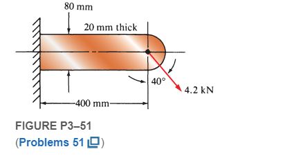
Chapter 3, Problem 51P
Compute the maximum tensile stress in the bracket shown in Figure P3−51.
Expert Solution & Answer
Want to see the full answer?
Check out a sample textbook solution
Students have asked these similar questions
Solve this problem and show all of the work
Given that an L-shaped member (OAB) can rotate about OA, determine the moment vector created by the force about the line OA at the instant shown in the figure below. OA lies in the xy-plane, and the AB part is vertical. Express your answer as a Cartesian vector.
Determine the magnitude of the moment created by the force about the point A.
Chapter 3 Solutions
Machine Elements in Mechanical Design (6th Edition) (What's New in Trades & Technology)
Ch. 3 - A tensile member in a machine structure is...Ch. 3 - Compute the stress in a round bar having a...Ch. 3 - Compute the stress in a rectangular bar having...Ch. 3 - A link in a packaging machine mechanism has a...Ch. 3 - Two circular rods support the 3800 lb weight of a...Ch. 3 - A tensile load of 5.00 kN is applied to a square...Ch. 3 - An aluminum rod is made in the form of a hollow...Ch. 3 - Compute the stress in the middle portion of rod AC...Ch. 3 - Compute the forces in the two angled rods in...Ch. 3 - If the rods from Problem 9 are circular, determine...
Ch. 3 - Repeat Problems 9 and 10 if the angle is 15 .Ch. 3 - Figure P312 shows a small truss spanning between...Ch. 3 - The truss shown in Figure P313 spans a total space...Ch. 3 - Figure P314 shows a short leg for a machine that...Ch. 3 - Consider the short compression member shown in...Ch. 3 - Refer Figure P38 . Each of the pins at A, B, and C...Ch. 3 - Compute the shear stress in the pins connecting...Ch. 3 - Prob. 18PCh. 3 - Prob. 19PCh. 3 - Prob. 20PCh. 3 - Prob. 21PCh. 3 - Compute the torsional shear stress in a circular...Ch. 3 - If the shaft of Problem 22 is 850 mm long and is...Ch. 3 - Compute the torsional shear stress due to a torque...Ch. 3 - Compute the torsional shear stress in a solid...Ch. 3 - Compute the torsional shear stress in a hollow...Ch. 3 - Compute the angle of twist for the hollow shaft of...Ch. 3 - A square steel bar, 25 mm on a side and 650 mm...Ch. 3 - A 3.00 in-diameter steel bar has a flat milled on...Ch. 3 - A commercial steel supplier lists rectangular...Ch. 3 - A beam is simply supported and carries the load...Ch. 3 - For each beam of Problem 31, compute its weight if...Ch. 3 - For each beam of Problem 31, compute the maximum...Ch. 3 - For the beam loading of Figure P334, draw the...Ch. 3 - For the beam loading of Figure P334, design the...Ch. 3 - Figure P336 shows a beam made from 4 in schedule...Ch. 3 - Select an aluminum I-beam shape to carry the load...Ch. 3 - Figure P338 represents a wood joist for a...Ch. 3 - For Problems 39 through 50, draw the free-body...Ch. 3 - Prob. 40PCh. 3 - For Problems 39 through 50, draw the free-body...Ch. 3 - Prob. 42PCh. 3 - Prob. 43PCh. 3 - Prob. 44PCh. 3 - For Problems 39 through 50, draw the free-body...Ch. 3 - For Problems 39 through 50, draw the free-body...Ch. 3 - For Problems 39 through 50, draw the free-body...Ch. 3 - For Problems 4850, draw the free-body diagram of...Ch. 3 - For Problems 4850, draw the free-body diagram of...Ch. 3 - Prob. 50PCh. 3 - Compute the maximum tensile stress in the bracket...Ch. 3 - Compute the maximum tensile and compressive...Ch. 3 - For the lever shown in Figure P353 (a), compute...Ch. 3 - Compute the maximum tensile stress at sections A...Ch. 3 - Prob. 55PCh. 3 - Refer to Figure P38. Compute the maximum tensile...Ch. 3 - Prob. 57PCh. 3 - Refer to P342. Compute the maximum stress in the...Ch. 3 - Refer to P343. Compute the maximum stress in the...Ch. 3 - Prob. 60PCh. 3 - Figure P361 shows a valve stem from an engine...Ch. 3 - The conveyor fixture shown in Figure P362 carries...Ch. 3 - For the flat plate in tension in Figure P363,...Ch. 3 - For Problems 64 through 68, compute the maximum...Ch. 3 - For Problems 64 through 68, compute the maximum...Ch. 3 - For Problems 64 through 68, compute the maximum...Ch. 3 - For Problems 64 through 68, compute the maximum...Ch. 3 - Prob. 68PCh. 3 - Figure P369 shows a horizontal beam supported by a...Ch. 3 - Prob. 70PCh. 3 - Prob. 71PCh. 3 - The beam shown in Figure P372 is a stepped, flat...Ch. 3 - Figure P373 shows a stepped, flat bar having a...Ch. 3 - Figure P374 shows a bracket carrying opposing...Ch. 3 - Prob. 75PCh. 3 - Figure P376 shows a lever made from a rectangular...Ch. 3 - For the lever in P376, determine the maximum...Ch. 3 - Figure P378 shows a shaft that is loaded only in...Ch. 3 - Prob. 79PCh. 3 - Prob. 80PCh. 3 - A hanger is made from ASTM A36 structural steel...Ch. 3 - A coping saw frame shown in Figure P382 is made...Ch. 3 - Prob. 83PCh. 3 - Figure P384 shows a hand garden tool used to break...Ch. 3 - Figure P385 shows a basketball backboard and goal...Ch. 3 - Prob. 86P
Knowledge Booster


Learn more about
Need a deep-dive on the concept behind this application? Look no further. Learn more about this topic, mechanical-engineering and related others by exploring similar questions and additional content below.Similar questions
- = MMB 241- Tutorial 1.pdf 2/3 80% + + 10. Determine a ats = 1 m v (m/s) 4 s (m) 2 11. Draw the v-t and s-t graphs if v = 0, s=0 when t=0. a (m/s²) 2 t(s) 12. Draw the v-t graph if v = 0 when t=0. Find the equation v = f(t) for each a (m/s²) 2 segment. 2 -2 13. Determine s and a when t = 3 s if s=0 when t = 0. v (m/s) 2 t(s) t(s) 2arrow_forwardQ.5) A cylinder is supported by spring AD and cables AB and AC as shown. The spring has an at rest length (unstretched length) of 4 meters. If the maximum allowable tension in cables AB and AC is 200 N, determine (a) the largest mass (kg) of cylinder E the system can support, (b) the necessary spring constant (stiffness) to maintain equilibrium, and (b) the tension (magnitude) in each cable when supporting the maximum load found in part (a). B 4 m 3 m A E 1 m 3 m D 5 marrow_forwardDetermine the moment created by the force about the point O. Express your answer as a Cartesian vector.arrow_forward
- 4. An impeller rotating at 1150 rpm has the following data: b, = 1 ¼ in., b2 = ¾ in., d, = 7 in., d2 = 15 in., B1 = 18", B2 = 20°, cross-sectional area A = Db if vane thickness is neglected. Assuming radial inlet flow, determine the theoretical capacity in gpm head in ft horsepower 5. If the impeller in Problem (4) develops an actual head of 82 ft and delivers 850 gpm at the point of maximum efficiency and requires 22 BHP. Determine overall pump efficiency virtual velocities V2 and W2arrow_forward(30 pts) Problem 1 A thin uniform rod of mass m and length 2r rests in a smooth hemispherical bowl of radius r. A moment M mgr 4 is applied to the rod. Assume that the bowl is fixed and its rim is in the horizontal plane. HINT: It will help you to find the length l of that portion of the rod that remains outside the bowl. M 2r a) How many degrees of freedom does this system have? b) Write an equation for the virtual work in terms of the angle 0 and the motion of the center of mass (TF) c) Derive an equation for the variation in the position of the center of mass (i.e., Sŕƒ) a. HINT: Use the center of the bowl as the coordinate system origin for the problem. d) In the case of no applied moment (i.e., M 0), derive an equation that can be used to solve for the equilibrium angle of the rod. DO NOT solve the equation e) In the case of an applied moment (i.e., M = mgr = -) derive an equation that can be used to 4 solve for the equilibrium angle of the rod. DO NOT solve the equation. f) Can…arrow_forwardPlease show all work step by steparrow_forward
- Copyright 2013 Pearson Education, publishing as Prentice Hall 2. Determine the force that the jaws J of the metal cutters exert on the smooth cable C if 100-N forces are applied to the handles. The jaws are pinned at E and A, and D and B. There is also a pin at F. E 400 mm 15° D B 30 mm² 80 mm/ 20 mm 15° $15° 20 mm 400 mm 15° 100 N 100 N 15°arrow_forwardDraw for it make a match which directionarrow_forwardQ.1) Block A is connected to block B by a pulley system as shown. The weights of blocks A and B are 100 lbs and 70 lbs, respectively. Assume negligible friction between the rope and all pulleys as well as between block B and the incline and neglect the mass of all pulleys and cables. Determine the angle 0 required to keep the system in equilibrium. (At least two FBDs must be drawn for full credit) B Ꮎ 000arrow_forward
- pls solvearrow_forward+1. 0,63 fin r= 0.051 P The stepped rod in sketch is subjected to a tensile force that varies between 4000 and 7000 lb. The rod has a machined surface finish everywhere except the shoulder area, where a grinding operation has been performed to improve the fatigue resistance of the rod. Using a 99% probability of survival, determine the safety factor for infinite life if the rod is made of AISI 1080 steel, quenched and tempered at 800°c Use the Goodman line. Does the part fail at the fillet? Explainarrow_forwardSolve this problem and show all of the workarrow_forward
arrow_back_ios
SEE MORE QUESTIONS
arrow_forward_ios
Recommended textbooks for you
 Mechanics of Materials (MindTap Course List)Mechanical EngineeringISBN:9781337093347Author:Barry J. Goodno, James M. GerePublisher:Cengage Learning
Mechanics of Materials (MindTap Course List)
Mechanical Engineering
ISBN:9781337093347
Author:Barry J. Goodno, James M. Gere
Publisher:Cengage Learning
Mechanical SPRING DESIGN Strategy and Restrictions in Under 15 Minutes!; Author: Less Boring Lectures;https://www.youtube.com/watch?v=dsWQrzfQt3s;License: Standard Youtube License