
Mechanics of Materials (10th Edition)
10th Edition
ISBN: 9780134319650
Author: Russell C. Hibbeler
Publisher: PEARSON
expand_more
expand_more
format_list_bulleted
Videos
Textbook Question
Chapter 10.5, Problem 10.28P
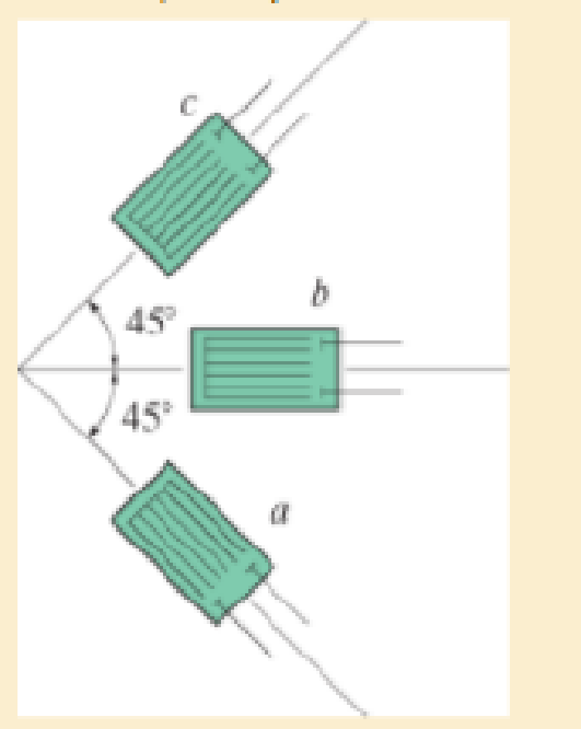
The following readings are obtained from each gage: εa = 800(10−6), εb = 520(10−6), εc = −450(10−6). Determine the in-plane principal strains.
Expert Solution & Answer

Learn your wayIncludes step-by-step video

schedule13:06
Students have asked these similar questions
Four-bar linkage mechanism, AB=40mm, BC=60mm, CD=70mm, AD=80mm, =60°, w1=10rad/s. Determine the direction and
magnitude of w3 using relative motion graphical method.
A
B
2
3
77777
477777
Four-bar linkage mechanism, AB=40mm, BC=60mm, CD=70mm, AD=80mm, =60°, w1=10rad/s. Determine the direction and
magnitude of w3 using relative motion graphical method.
A
B
2
3
77777
477777
The evaporator of a vapor compression refrigeration cycle utilizing R-123 as the refrigerant isbeing used to chill water. The evaporator is a shell and tube heat exchanger with the water flowingthrough the tubes. The water enters the heat exchanger at a temperature of 54°F. The approachtemperature difference of the evaporator is 3°R. The evaporating pressure of the refrigeration cycleis 4.8 psia and the condensing pressure is 75 psia. The refrigerant is flowing through the cycle witha flow rate of 18,000 lbm/hr. The R-123 leaves the evaporator as a saturated vapor and leaves thecondenser as a saturated liquid. Determine the following:a. The outlet temperature of the chilled waterb. The volumetric flow rate of the chilled water (gpm)c. The UA product of the evaporator (Btu/h-°F)d. The heat transfer rate between the refrigerant and the water (tons)
Chapter 10 Solutions
Mechanics of Materials (10th Edition)
Ch. 10.3 - Prove that the sum of the normal strains in...Ch. 10.3 - The state of strain at the point on the arm has...Ch. 10.3 - The state of strain at the point on the pin leaf...Ch. 10.3 - The state of strain at the point on the pin leaf...Ch. 10.3 - The state of strain at the point on the leaf of...Ch. 10.3 - Use the strain transformation equations and...Ch. 10.3 - Use the strain transformation equations and...Ch. 10.3 - Use the strain transformation equations to...Ch. 10.3 - Use the strain transformation equations to...Ch. 10.3 - Use the strain- transformation equations to...
Ch. 10.3 - Use the strain transformation equations to...Ch. 10.3 - Determine the equivalent state of strain on an...Ch. 10.3 - Determine the equivalent state of strain which...Ch. 10.3 - Use the strain transformation equations to...Ch. 10.3 - Determine the equivalent state of strain, which...Ch. 10.3 - Solve Prob.103 using Mohrs circle. 103. The state...Ch. 10.3 - using Mohrs circle. 103. The state of strain at...Ch. 10.3 - Solve Prob.105 using Mohrs circle. 105. The state...Ch. 10.3 - Solve Prob.108 using Mohrs circle 108. The state...Ch. 10.3 - using Mohrs circle. 106. The state of strain at a...Ch. 10.5 - The strain at point A on the bracket has...Ch. 10.5 - Determine (a) the principal strains at A, (b) the...Ch. 10.5 - Determine (a) the principal strains at A, in the...Ch. 10.5 - The following readings are obtained for each gage:...Ch. 10.5 - The following readings are obtained for each gage:...Ch. 10.5 - The following readings are obtained for each gage:...Ch. 10.5 - The following readings are obtained from each...Ch. 10.6 - For the case of plane stress, show that Hookes law...Ch. 10.6 - to develop the strain tranformation equations....Ch. 10.6 - Determine the modulus of elasticity and Polssons...Ch. 10.6 - If it is subjected to an axial load of 15 N such...Ch. 10.6 - If it has the original dimensions shown, determine...Ch. 10.6 - If it has the original dimensions shown, determine...Ch. 10.6 - A strain gage having a length of 20 mm Is attached...Ch. 10.6 - Determine the bulk modulus for each of the...Ch. 10.6 - The strain gage is placed on the surface of the...Ch. 10.6 - Determine the associated principal stresses at the...Ch. 10.6 - Determine the applied load P. What is the shear...Ch. 10.6 - If a load of P = 3 kip is applied to the A-36...Ch. 10.6 - The cube of aluminum is subjected to the three...Ch. 10.6 - The principal strains at a point on the aluminum...Ch. 10.6 - A uniform edge load of 500 lb/in. and 350 lb/in....Ch. 10.6 - Prob. 10.45PCh. 10.6 - A single strain gage, placed in the vertical plane...Ch. 10.6 - A single strain gage, placed in the vertical plane...Ch. 10.6 - If the material is graphite for which Eg = 800 ksi...Ch. 10.6 - Determine the normal stresses x and y in the plate...Ch. 10.6 - The steel shaft has a radius of 15 mm. Determine...Ch. 10.6 - Prob. 10.51PCh. 10.6 - The A-36 steel pipe is subjected to the axial...Ch. 10.6 - Air is pumped into the steel thin-walled pressure...Ch. 10.6 - Air is pumped into the steel thin-walled pressure...Ch. 10.6 - Prob. 10.55PCh. 10.6 - The thin-walled cylindrical pressure vessel of...Ch. 10.6 - The thin-walled cylindrical pressure vessel of...Ch. 10.6 - Prob. 10.58PCh. 10.7 - A material is subjected to plane stress. Express...Ch. 10.7 - A material is subjected to plane stress. Express...Ch. 10.7 - The yield stress for a zirconium-magnesium alloy...Ch. 10.7 - Solve Prob. 1061 using the maximum distortion...Ch. 10.7 - If a machine part is made of tool L2 steel and a...Ch. 10.7 - Solve Prob.1063 using the maximum distortion...Ch. 10.7 - Prob. 10.65PCh. 10.7 - If a shaft is made of a material for which y = 75...Ch. 10.7 - Solve Prob.1066 using the maximum shear stress...Ch. 10.7 - If the material is machine steel having a yield...Ch. 10.7 - The short concrete cylinder having a diameter of...Ch. 10.7 - Prob. 10.70PCh. 10.7 - The plate is made of Tobin bronze, which yields at...Ch. 10.7 - The plate is made of Tobin bronze, which yields at...Ch. 10.7 - An aluminum alloy is to be used for a solid drive...Ch. 10.7 - If a machine part is made of titanium (TI-6A1-4V)...Ch. 10.7 - The components of plane stress at a critical point...Ch. 10.7 - The components of plane stress at a critical point...Ch. 10.7 - The 304-stainless-steel cylinder has an inner...Ch. 10.7 - The 304-stainless-steel cylinder has an inner...Ch. 10.7 - If the 2-in diameter shaft is made from brittle...Ch. 10.7 - If the 2-in diameter shaft is made from cast iron...Ch. 10.7 - If Y = 50 ksi, determine the factor of safety for...Ch. 10.7 - Prob. 10.82PCh. 10.7 - If the yield stress for steel is Y = 36 ksi,...Ch. 10.7 - Prob. 10.84PCh. 10.7 - The state of stress acting at a critical point on...Ch. 10.7 - The shaft consists of a solid segment AB and a...Ch. 10.7 - The shaft consists of a solid segment AB and a...Ch. 10.7 - Prob. 10.88PCh. 10.7 - If Y = 50 ksi, determine the factor of safety for...Ch. 10.7 - The gas tank is made from A-36 steel and has an...Ch. 10.7 - The internal loadings at a critical section along...Ch. 10.7 - If the material is machine steel having a yield...Ch. 10.7 - If the material is machine steel having a yield...Ch. 10 - In the case of plane stress, where the in-plane...Ch. 10 - The plate is made of material having a modulus of...Ch. 10 - If the material is machine steel having a yield...Ch. 10 - Determine if yielding has occurred on the basis of...Ch. 10 - The 60 strain rosette is mounted on a beam. The...Ch. 10 - Use the strain transformation equations to...Ch. 10 - If the strain gages a and b at points give...Ch. 10 - Use the strain-transformation equations and...Ch. 10 - Use the strain transformation equations to...Ch. 10 - Specify the orientation of the corresponding...
Additional Engineering Textbook Solutions
Find more solutions based on key concepts
While researching fluid dynamics, you came across a reference to the dimensionless number called the capillary ...
Thinking Like an Engineer: An Active Learning Approach (4th Edition)
If you call the index method to locate an item in a list and the item is not found, this happens. a. A ValueErr...
Starting Out with Python (4th Edition)
Tail Program Write a program that asks the user for the name of a file. The program should display the last ten...
Starting Out with C++ from Control Structures to Objects (9th Edition)
What is the purpose of the hole-circle plate on a universal dividing head?
Degarmo's Materials And Processes In Manufacturing
Determine the resultant internal normal force, shear force, and bending moment at point C in the beam.
Mechanics of Materials (10th Edition)
Write a program to read a list of nonnegative integers and to display the largest integer, the smallest integer...
Java: An Introduction to Problem Solving and Programming (8th Edition)
Knowledge Booster


Learn more about
Need a deep-dive on the concept behind this application? Look no further. Learn more about this topic, mechanical-engineering and related others by exploring similar questions and additional content below.Similar questions
- (Read image) (Answer given)arrow_forwardProblem (17): water flowing in an open channel of a rectangular cross-section with width (b) transitions from a mild slope to a steep slope (i.e., from subcritical to supercritical flow) with normal water depths of (y₁) and (y2), respectively. Given the values of y₁ [m], y₂ [m], and b [m], calculate the discharge in the channel (Q) in [Lit/s]. Givens: y1 = 4.112 m y2 = 0.387 m b = 0.942 m Answers: ( 1 ) 1880.186 lit/s ( 2 ) 4042.945 lit/s ( 3 ) 2553.11 lit/s ( 4 ) 3130.448 lit/sarrow_forwardProblem (14): A pump is being used to lift water from an underground tank through a pipe of diameter (d) at discharge (Q). The total head loss until the pump entrance can be calculated as (h₁ = K[V²/2g]), h where (V) is the flow velocity in the pipe. The elevation difference between the pump and tank surface is (h). Given the values of h [cm], d [cm], and K [-], calculate the maximum discharge Q [Lit/s] beyond which cavitation would take place at the pump entrance. Assume Turbulent flow conditions. Givens: h = 120.31 cm d = 14.455 cm K = 8.976 Q Answers: (1) 94.917 lit/s (2) 49.048 lit/s ( 3 ) 80.722 lit/s 68.588 lit/s 4arrow_forward
- Problem (13): A pump is being used to lift water from the bottom tank to the top tank in a galvanized iron pipe at a discharge (Q). The length and diameter of the pipe section from the bottom tank to the pump are (L₁) and (d₁), respectively. The length and diameter of the pipe section from the pump to the top tank are (L2) and (d2), respectively. Given the values of Q [L/s], L₁ [m], d₁ [m], L₂ [m], d₂ [m], calculate total head loss due to friction (i.e., major loss) in the pipe (hmajor-loss) in [cm]. Givens: L₁,d₁ Pump L₂,d2 오 0.533 lit/s L1 = 6920.729 m d1 = 1.065 m L2 = 70.946 m d2 0.072 m Answers: (1) 3.069 cm (2) 3.914 cm ( 3 ) 2.519 cm ( 4 ) 1.855 cm TABLE 8.1 Equivalent Roughness for New Pipes Pipe Riveted steel Concrete Wood stave Cast iron Galvanized iron Equivalent Roughness, & Feet Millimeters 0.003-0.03 0.9-9.0 0.001-0.01 0.3-3.0 0.0006-0.003 0.18-0.9 0.00085 0.26 0.0005 0.15 0.045 0.000005 0.0015 0.0 (smooth) 0.0 (smooth) Commercial steel or wrought iron 0.00015 Drawn…arrow_forwardThe flow rate is 12.275 Liters/s and the diameter is 6.266 cm.arrow_forwardAn experimental setup is being built to study the flow in a large water main (i.e., a large pipe). The water main is expected to convey a discharge (Qp). The experimental tube will be built at a length scale of 1/20 of the actual water main. After building the experimental setup, the pressure drop per unit length in the model tube (APm/Lm) is measured. Problem (20): Given the value of APm/Lm [kPa/m], and assuming pressure coefficient similitude, calculate the drop in the pressure per unit length of the water main (APP/Lp) in [Pa/m]. Givens: AP M/L m = 590.637 kPa/m meen Answers: ( 1 ) 59.369 Pa/m ( 2 ) 73.83 Pa/m (3) 95.443 Pa/m ( 4 ) 44.444 Pa/m *******arrow_forward
- Find the reaction force in y if Ain = 0.169 m^2, Aout = 0.143 m^2, p_in = 0.552 atm, Q = 0.367 m^3/s, α = 31.72 degrees. The pipe is flat on the ground so do not factor in weight of the pipe and fluid.arrow_forwardFind the reaction force in x if Ain = 0.301 m^2, Aout = 0.177 m^2, p_in = 1.338 atm, Q = 0.669 m^3/s, and α = 37.183 degreesarrow_forwardProblem 5: Three-Force Equilibrium A structural connection at point O is in equilibrium under the action of three forces. • • . Member A applies a force of 9 kN vertically upward along the y-axis. Member B applies an unknown force F at the angle shown. Member C applies an unknown force T along its length at an angle shown. Determine the magnitudes of forces F and T required for equilibrium, assuming 0 = 90° y 9 kN Aarrow_forward
- Problem 19: Determine the force in members HG, HE, and DE of the truss, and state if the members are in tension or compression. 4 ft K J I H G B C D E F -3 ft -3 ft 3 ft 3 ft 3 ft- 1500 lb 1500 lb 1500 lb 1500 lb 1500 lbarrow_forwardProblem 14: Determine the reactions at the pin A, and the tension in cord. Neglect the thickness of the beam. F1=26kN F2 13 12 80° -2m 3marrow_forwardProblem 22: Determine the force in members GF, FC, and CD of the bridge truss and state if the members are in tension or compression. F 15 ft B D -40 ft 40 ft -40 ft 40 ft- 5 k 10 k 15 k 30 ft Earrow_forward
arrow_back_ios
SEE MORE QUESTIONS
arrow_forward_ios
Recommended textbooks for you
 Elements Of ElectromagneticsMechanical EngineeringISBN:9780190698614Author:Sadiku, Matthew N. O.Publisher:Oxford University Press
 Mechanics of Materials (10th Edition)Mechanical EngineeringISBN:9780134319650Author:Russell C. HibbelerPublisher:PEARSON
 Thermodynamics: An Engineering ApproachMechanical EngineeringISBN:9781259822674Author:Yunus A. Cengel Dr., Michael A. BolesPublisher:McGraw-Hill Education
 Control Systems EngineeringMechanical EngineeringISBN:9781118170519Author:Norman S. NisePublisher:WILEY
 Mechanics of Materials (MindTap Course List)Mechanical EngineeringISBN:9781337093347Author:Barry J. Goodno, James M. GerePublisher:Cengage Learning
 Engineering Mechanics: StaticsMechanical EngineeringISBN:9781118807330Author:James L. Meriam, L. G. Kraige, J. N. BoltonPublisher:WILEY
Elements Of Electromagnetics
Mechanical Engineering
ISBN:9780190698614
Author:Sadiku, Matthew N. O.
Publisher:Oxford University Press
Mechanics of Materials (10th Edition)
Mechanical Engineering
ISBN:9780134319650
Author:Russell C. Hibbeler
Publisher:PEARSON
Thermodynamics: An Engineering Approach
Mechanical Engineering
ISBN:9781259822674
Author:Yunus A. Cengel Dr., Michael A. Boles
Publisher:McGraw-Hill Education
Control Systems Engineering
Mechanical Engineering
ISBN:9781118170519
Author:Norman S. Nise
Publisher:WILEY
Mechanics of Materials (MindTap Course List)
Mechanical Engineering
ISBN:9781337093347
Author:Barry J. Goodno, James M. Gere
Publisher:Cengage Learning
Engineering Mechanics: Statics
Mechanical Engineering
ISBN:9781118807330
Author:James L. Meriam, L. G. Kraige, J. N. Bolton
Publisher:WILEY
Lec21, Part 5, Strain transformation; Author: Mechanics of Materials (Libre);https://www.youtube.com/watch?v=sgJvz5j_ubM;License: Standard Youtube License