
Microelectronics: Circuit Analysis and Design
4th Edition
ISBN: 9780073380643
Author: Donald A. Neamen
Publisher: McGraw-Hill Companies, The
expand_more
expand_more
format_list_bulleted
Videos
Textbook Question
Chapter 8, Problem 8.17P
Consider the class−A source−follower circuit shown in Figure P8.17. The transistors are matched with parameters
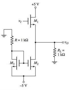
Figure P8.17
Expert Solution & Answer
Want to see the full answer?
Check out a sample textbook solution
Students have asked these similar questions
Do you happen to know what is the complete circuit?
b) Draw the magnitude and phase bode plot
c) Given Cdb=0.02pF, how will the frequency response change, draw the resulting magnitude and phase bode plotplz help me to solve part b and c.
Medium 1 is a lossless dielectric (ε₁, μ₁ = μo, σ₁ = 0)
Medium 2 is a perfect electric conductor (PEC) ( 2 = 0, μ2 = μo, σ₂ = ∞)
[ Moσ = 0] [ε0 μ₁ σ₂ = ∞ ] (J=σE is finite, E = 0)
E(z) Exe² +Пe₁²]
1. For the case εr] =
λι =
=
E2(z)-0
-
1 (vacuum), E₁x 1 V/m and a frequency f = 500 MHz determine:
n₁ =
12=
2. Determine:
r =
T=
3. Using this I show that the total electric field E₁0(z) in region 1 can be written as:
E(z) = -2jE, sin(2лz/λ)✰
4. The magnitude E10(z) will show an interference pattern. The SWR (standing wave ratio) is the
Emax/Emin ratio of the magnitude of the total electric field in region 1. What is the SWR?
E (z) = 2|E|sin(2лz/2₁)|
E" (z)
SWR A
Imax
E(z)
Imin
1+r
1-||
tot
5. Roughly SKETCH the magnitude of E10(z) and E20(z) on the graph below.
E₁tot(z)
tot
E20(z)
-0.40
-0.30
-0.ło
z=0
+0.1b +0.20
Chapter 8 Solutions
Microelectronics: Circuit Analysis and Design
Ch. 8 - Prob. 8.1EPCh. 8 - Prob. 8.2EPCh. 8 - Prob. 8.3EPCh. 8 - Prob. 8.1TYUCh. 8 - Prob. 8.2TYUCh. 8 - Prob. 8.3TYUCh. 8 - Prob. 8.4EPCh. 8 - Prob. 8.5EPCh. 8 - Prob. 8.7EPCh. 8 - Prob. 8.4TYU
Ch. 8 - Prob. 8.5TYUCh. 8 - Prob. 8.6TYUCh. 8 - A transformercoupled emitterfollower amplifier is...Ch. 8 - Prob. 8.7TYUCh. 8 - Prob. 8.9EPCh. 8 - Prob. 8.11EPCh. 8 - Consider the classAB output stage shown in Figure...Ch. 8 - From Figure 8.36, show that the overall current...Ch. 8 - Prob. 1RQCh. 8 - Describe the safe operating area for a transistor.Ch. 8 - Why is an interdigitated structure typically used...Ch. 8 - Discuss the role of thermal resistance between...Ch. 8 - Define and describe the power derating curve for a...Ch. 8 - Define power conversion efficiency for an output...Ch. 8 - Prob. 7RQCh. 8 - Describe the operation of an ideal classB output...Ch. 8 - Discuss crossover distortion.Ch. 8 - What is meant by harmonic distortion?Ch. 8 - Describe the operation of a classAB output stage...Ch. 8 - Describe the operation of a transformercoupled...Ch. 8 - Prob. 13RQCh. 8 - Sketch a classAB complementary MOSFET pushpull...Ch. 8 - What are the advantages of a Darlington pair...Ch. 8 - Sketch a twotransistor configuration using npn and...Ch. 8 - Prob. 8.1PCh. 8 - Prob. 8.2PCh. 8 - Prob. 8.3PCh. 8 - Prob. 8.4PCh. 8 - Prob. 8.5PCh. 8 - Prob. D8.6PCh. 8 - A particular transistor is rated for a maximum...Ch. 8 - Prob. 8.8PCh. 8 - For a power MOSFET, devcase=1.5C/W , snkamb=2.8C/W...Ch. 8 - Prob. 8.10PCh. 8 - The quiescent collector current in a BiT is ICQ=3A...Ch. 8 - Prob. 8.12PCh. 8 - Prob. 8.13PCh. 8 - Prob. 8.14PCh. 8 - Prob. 8.15PCh. 8 - Prob. 8.16PCh. 8 - Consider the classA sourcefollower circuit shown...Ch. 8 - Prob. 8.18PCh. 8 - Prob. 8.19PCh. 8 - Prob. 8.20PCh. 8 - Prob. 8.21PCh. 8 - Consider an idealized classB output stage shown in...Ch. 8 - Consider an idealized classB output stage shown in...Ch. 8 - Prob. 8.24PCh. 8 - For the classB output stage shown in Figure P8.24,...Ch. 8 - Prob. 8.26PCh. 8 - Prob. 8.27PCh. 8 - Consider the classAB output stage in Figure P8.28....Ch. 8 - Prob. 8.29PCh. 8 - Prob. D8.30PCh. 8 - Prob. 8.31PCh. 8 - Prob. D8.32PCh. 8 - Consider the transformercoupled commonemitter...Ch. 8 - The parameters for the transformercoupled...Ch. 8 - A BJT emitter follower is coupled to a load with...Ch. 8 - Consider the transformercoupled emitter follower...Ch. 8 - A classA transformer-coupled emitter follower must...Ch. 8 - Repeat Problem 8.36 if the primary side of the...Ch. 8 - Consider the circuit in Figure 8.31. The circuit...Ch. 8 - Prob. D8.40PCh. 8 - The value of IBiass in the circuit shown in Figure...Ch. 8 - The transistors in the output stage in Figure 8.34...Ch. 8 - Consider the circuit in Figure 8.34. The supply...Ch. 8 - Prob. 8.44PCh. 8 - Prob. 8.45PCh. 8 - Consider the classAB MOSFET output stage shown in...Ch. 8 - Prob. 8.47PCh. 8 - Consider the classAB output stage in Figure P8.48....Ch. 8 - For the classAB output stage in Figure 8.36, the...
Knowledge Booster


Learn more about
Need a deep-dive on the concept behind this application? Look no further. Learn more about this topic, electrical-engineering and related others by exploring similar questions and additional content below.Similar questions
- would anyone be able to tell me the amount of wire needed for this electrical plan in this house? and if possible would anyone be able to tell me the amount of any other materials needed (wire sizes, box sizes/styles)arrow_forwardPlease show all stepsarrow_forwardA plane wave propagating in the +z direction in medium 1 is normally incident to medium 2 located at the z=0 plane as below. Both mediums are general, characterized by ( ε i, Mi, Ơi ). tot = [ ει μη σ] [ε, μη σε ] Ex Ex tot E₁₂ (z) = Ee Ex z=0 From conservation of energy: P₁AV'(z=0) + Piav'(z=0) = P2av²(z=0). Using the above show for lossless media that: ( 1 - ||²) = (1/M2 )|T|² .arrow_forward
- A plane wave propagating in the +z direction in medium 1 is normally incident to medium 2 located at the z=0 plane as below. Both mediums are general, characterized by ( ε i, Hi, σ¡ ). [ ει μη σ] Ex [ ει μη ση ] Ex tot E₁₂ (z) = E'₁e¹² -122 E(z) = Ee+ E₁₁₁² E₁x z=0 1. Specify the electric field reflection coefficient г and transmission coefficient T: E ΓΔ E E TA EL 2. Show that T=1+г. Can the transmitted electric field amplitude in region 2 be LARGER than the incident electric field amplitude? 3. Determine expressions for P₁AV'(z), PIAV'(z) and P2AV'(z) (note the sign for the reflected power direction should be (-z).arrow_forward2) In the ideal transformer circuit shown below find Vo and the complex power supplied by the source. 292 www b 1:4 16 Ω ww + + 240/0° V rms -12492arrow_forward3) In the ideal autotransformer circuit shown below find 11, 12 and lo. Find the average power delivered to the load. (hint: write KVL for both sides) 20/30° V(+ 2-1602 200 turns V₂ 10 + j40 Ω 80 turns V₁arrow_forward
- 1) Find Vo in the following circuit. Assume the mesh currents are clockwise. ΠΩ Ω ΖΩ ww 1Ω ww 24/0° (± 6 Ω j4 Ω 1Ω +arrow_forwardPlease show all stepsarrow_forward11-3) similar to Lathi & Ding, Prob. P.6.8-1 Consider the carrier modulator shown in the figure below, which transmits a binary carrier signal. The baseband generator uses polar NRZ signaling with rectangular pulses. The data rate is 8 Mbit/s. (a) If the modulator generates a binary PSK signal, what is the bandwidth of the modulated output? (b) If the modulator generates FSK with the difference fel - fco = 6 MHz (cf. Fig 6.32c), determine the modulated signal bandwidth. Binary data source Baseband signal generator Modulated output Modulator N-E---arrow_forward
arrow_back_ios
SEE MORE QUESTIONS
arrow_forward_ios
Recommended textbooks for you
 Introductory Circuit Analysis (13th Edition)Electrical EngineeringISBN:9780133923605Author:Robert L. BoylestadPublisher:PEARSON
 Delmar's Standard Textbook Of ElectricityElectrical EngineeringISBN:9781337900348Author:Stephen L. HermanPublisher:Cengage Learning
 Programmable Logic ControllersElectrical EngineeringISBN:9780073373843Author:Frank D. PetruzellaPublisher:McGraw-Hill Education
 Fundamentals of Electric CircuitsElectrical EngineeringISBN:9780078028229Author:Charles K Alexander, Matthew SadikuPublisher:McGraw-Hill Education
 Electric Circuits. (11th Edition)Electrical EngineeringISBN:9780134746968Author:James W. Nilsson, Susan RiedelPublisher:PEARSON
 Engineering ElectromagneticsElectrical EngineeringISBN:9780078028151Author:Hayt, William H. (william Hart), Jr, BUCK, John A.Publisher:Mcgraw-hill Education,
Introductory Circuit Analysis (13th Edition)
Electrical Engineering
ISBN:9780133923605
Author:Robert L. Boylestad
Publisher:PEARSON
Delmar's Standard Textbook Of Electricity
Electrical Engineering
ISBN:9781337900348
Author:Stephen L. Herman
Publisher:Cengage Learning
Programmable Logic Controllers
Electrical Engineering
ISBN:9780073373843
Author:Frank D. Petruzella
Publisher:McGraw-Hill Education
Fundamentals of Electric Circuits
Electrical Engineering
ISBN:9780078028229
Author:Charles K Alexander, Matthew Sadiku
Publisher:McGraw-Hill Education
Electric Circuits. (11th Edition)
Electrical Engineering
ISBN:9780134746968
Author:James W. Nilsson, Susan Riedel
Publisher:PEARSON
Engineering Electromagnetics
Electrical Engineering
ISBN:9780078028151
Author:Hayt, William H. (william Hart), Jr, BUCK, John A.
Publisher:Mcgraw-hill Education,
Diode Logic Gates - OR, NOR, AND, & NAND; Author: The Organic Chemistry Tutor;https://www.youtube.com/watch?v=9lqwSaIDm2g;License: Standard Youtube License