
Concept explainers
(a)
To sketch:The safe operating area for the transistor and the load line on the same graph.
(a)
Answer to Problem 8.5P
Thearea for the safe operation of the transistor and the load line for the transistor is shown in Figure 1.
Explanation of Solution
Calculation:
The sketch for the safe operating area of the transistor is shown below.
The required diagram is shown in Figure 1
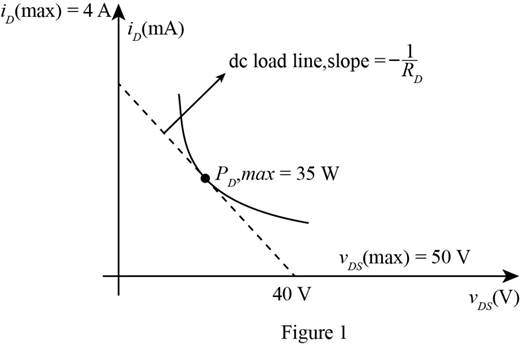
The above figure shows the safe region under which the transistor must be operated. The graph is plotted under the linear current and voltage scale. The sketch for the load line is dotted and is given by
Conclusion:
Therefore, the area for the safe operation of the transistor and the load line for the transistor is shown in Figure 1
(b)
The value of the drain current.
(b)
Answer to Problem 8.5P
Thepower at
Explanation of Solution
Calculation:
The expression for the voltage
The expression for the drain current is given by,
Substitute
The expression for the drain to source voltage is given by,
Substitute
The expression for the power dissipation is given by,
Substitute
Substitute
Substitute
Substitute
Substitute
Substitute
Substitute
The expression for the drain current in the non saturated region is given by,
Substitute
The expression for the drain current by ohm’s law is given by,
Substitute
Substitute
Substitute
Substitute
Substitute
Substitute
Substitute
Substitute
Conclusion:
Therefore, the power at
(c)
Whether there is a possibility of transistor getting damage.
(c)
Answer to Problem 8.5P
Yes, thetransistor will get damaged at
Explanation of Solution
The power of the transistor at
The above power is greater than the rated power of the transistor this means that the transistor gets damaged at
Want to see more full solutions like this?
Chapter 8 Solutions
Microelectronics: Circuit Analysis and Design


- + V 6.2 A 1.2 A S R 4 Ω Find the source voltage Vs 0.8 Aarrow_forwardDetermine i(t) for t≥ 0 given that the circuit below had been in steady state for a long time prior to t = 0. Also, I₁ = 1 5 A, R₁ =22, R2 =10 Q2, R3 = 32, R4 =7 2, and L=0.15 H. Also fill the table. m L ww R2 t = 0 R₁ 29 R3 R4 Time 0 iL(t) 0 8arrow_forwardPlease help explain this problemarrow_forward
- + P = 16 W w w P = 8 W I R₁ R2 E = RT=322 1- Determine R1, R2, E ΙΩarrow_forward+ 30 V = - 20 V + R 2- Use KVL to find the voltage V - V + + 8 Varrow_forwardFind the Thévenin equivalent circuit for the portions of the networks in Figure external to the elements between points a and b. a R₁ 2002 I = 0.1 A 0° Xc : 32 Ω R2 = 6802 20 Ω фъarrow_forward
- Find the Norton equivalent circuit for the network external to the elements between a and b for the networks in Figure. E1 = 120 V Z 0° R ww 10 Ω Xc XL · 000 802 802 ① I = 0.5 AZ 60° ZL barrow_forwardUsing superposition, determine the current through inductance XL for each network in Figure I = 0.3 A 60° XL 000 802 XC 502 Ω E 10 V0° =arrow_forwardFind the Thévenin equivalent circuit for the portions of the networks in Figure external to the elements between points a and b. E = 20 VZ0° + R ww 2 ΚΩ Хо XL 000 6ΚΩ 3 ΚΩ b RLarrow_forward
- What percentage of the full-load current of a thermally protected continuous-duty motor of more than one Hp can the trip current be, if the full-load current is 15 amperes? Ο 122 Ο 140 156 O 170arrow_forwardQ3arrow_forwardIn thinkercad can you make a parallel series circuit with a resistors and a voltage source explain how the voltage and current moves through the circuit, and explaining all the components, and if you were to break the circuit to find the current how would you do that? Please show visuals if possible.arrow_forward
 Introductory Circuit Analysis (13th Edition)Electrical EngineeringISBN:9780133923605Author:Robert L. BoylestadPublisher:PEARSON
 Delmar's Standard Textbook Of ElectricityElectrical EngineeringISBN:9781337900348Author:Stephen L. HermanPublisher:Cengage Learning
 Programmable Logic ControllersElectrical EngineeringISBN:9780073373843Author:Frank D. PetruzellaPublisher:McGraw-Hill Education
 Fundamentals of Electric CircuitsElectrical EngineeringISBN:9780078028229Author:Charles K Alexander, Matthew SadikuPublisher:McGraw-Hill Education
 Electric Circuits. (11th Edition)Electrical EngineeringISBN:9780134746968Author:James W. Nilsson, Susan RiedelPublisher:PEARSON
 Engineering ElectromagneticsElectrical EngineeringISBN:9780078028151Author:Hayt, William H. (william Hart), Jr, BUCK, John A.Publisher:Mcgraw-hill Education,