
Videos
Consider the class−AB output stage in Figure P8.48. The parameters are:
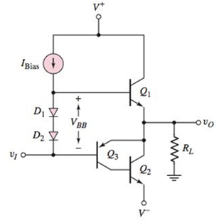
Figure P8.48
(a)
The value of
Answer to Problem 8.48P
Thevalue of the voltage
Explanation of Solution
Calculation:
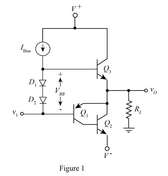
The given diagram is shown in Figure 1
The conversion from
The conversion from
The expression for the value of
Substitute
The expression for the value of the current
The expression for the value of the current
The expression for the value of the current
Substitute
The expression for the value of the current
The expression for the value of the current
The expression for the value of base to emitter voltage
The expression for the value of base to emitter voltage
The expression for the value of
Substitute
Substitute
Substitute
The expression for the value of base to emitter voltage
The expression for the value of base to emitter voltage
The expression for the value of the base to emitter voltage
Substitute
Substitute
Substitute
Substitute
The expression for the value of the current
Substitute
Substitute
Substitute
Substitute
The expression for the value of the voltage
Substitute
Conclusion:
Therefore, the value of the voltage
(b)
The value of
Answer to Problem 8.48P
The value of power delivered
Explanation of Solution
Calculation:
The expression for the value of the current
Substitute
The expression for the voltage
Substitute
The expression for the voltage
Substitute
The expression for the value of the voltage is given by,
Substitute
The expression for the value of the current for
Substitute
The expression for the value of the power delivered to the load is given by,
Substitute
The expression for the power delivered in the transistor of
Substitute
The expression for the power delivered in the transistor of
Substitute
The expression for the value of the current
Substitute
The expression for the value of the power dissipated in the transistor
Substitute
Conclusion:
Therefore, the value of power delivered
Want to see more full solutions like this?
Chapter 8 Solutions
Microelectronics: Circuit Analysis and Design


- + P = 16 W w w P = 8 W I R₁ R2 E = RT=322 1- Determine R1, R2, E ΙΩarrow_forward+ 30 V = - 20 V + R 2- Use KVL to find the voltage V - V + + 8 Varrow_forwardFind the Thévenin equivalent circuit for the portions of the networks in Figure external to the elements between points a and b. a R₁ 2002 I = 0.1 A 0° Xc : 32 Ω R2 = 6802 20 Ω фъarrow_forward
- Find the Norton equivalent circuit for the network external to the elements between a and b for the networks in Figure. E1 = 120 V Z 0° R ww 10 Ω Xc XL · 000 802 802 ① I = 0.5 AZ 60° ZL barrow_forwardUsing superposition, determine the current through inductance XL for each network in Figure I = 0.3 A 60° XL 000 802 XC 502 Ω E 10 V0° =arrow_forwardFind the Thévenin equivalent circuit for the portions of the networks in Figure external to the elements between points a and b. E = 20 VZ0° + R ww 2 ΚΩ Хо XL 000 6ΚΩ 3 ΚΩ b RLarrow_forward
- What percentage of the full-load current of a thermally protected continuous-duty motor of more than one Hp can the trip current be, if the full-load current is 15 amperes? Ο 122 Ο 140 156 O 170arrow_forwardQ3arrow_forwardIn thinkercad can you make a parallel series circuit with a resistors and a voltage source explain how the voltage and current moves through the circuit, and explaining all the components, and if you were to break the circuit to find the current how would you do that? Please show visuals if possible.arrow_forward
- In thinkercad can you make a series circuit with a resistors and a voltage source explain how the voltage and current moves through the circuit, and explaining all the components, and if you were to break the circuit to find the current how would you do that? Please show visuals if possible.arrow_forwardIn thinkercad can you make a parallel circuit with a resistors and a voltage source explain how the voltage and current moves through the circuit, and explaining all the components, and if you were to break the circuit to find the current how would you do that? Please show visuals if possiblearrow_forwardQ1arrow_forward
 Introductory Circuit Analysis (13th Edition)Electrical EngineeringISBN:9780133923605Author:Robert L. BoylestadPublisher:PEARSON
 Delmar's Standard Textbook Of ElectricityElectrical EngineeringISBN:9781337900348Author:Stephen L. HermanPublisher:Cengage Learning
 Programmable Logic ControllersElectrical EngineeringISBN:9780073373843Author:Frank D. PetruzellaPublisher:McGraw-Hill Education
 Fundamentals of Electric CircuitsElectrical EngineeringISBN:9780078028229Author:Charles K Alexander, Matthew SadikuPublisher:McGraw-Hill Education
 Electric Circuits. (11th Edition)Electrical EngineeringISBN:9780134746968Author:James W. Nilsson, Susan RiedelPublisher:PEARSON
 Engineering ElectromagneticsElectrical EngineeringISBN:9780078028151Author:Hayt, William H. (william Hart), Jr, BUCK, John A.Publisher:Mcgraw-hill Education,