
Videos
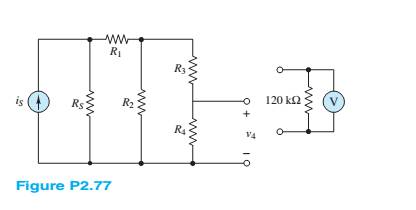
A voltmeter is used to determine the voltage acrossa resistive element in the circuit of Figure P2.77. The instrument is modeled by an ideal voltmeter in parallel with a
a.
b.
c.
d.
(a)
The voltage across R4 with and without voltmeter for the given value.
Answer to Problem 2.77HP
Without the voltmeter
With the voltmeter:
Explanation of Solution
Given information:
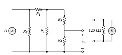
The given circuit is shown below.
Calculation:
Assuming that voltmeter is ideal in parallel with 120-ohm resister.
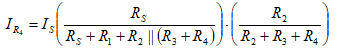
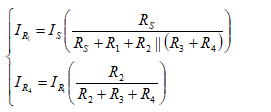
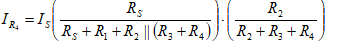
First develop an expression for VR4 in terms of R4 ,using current division
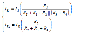
Therefore,
Hence,without the voltmeter
Now find the voltage drop across
With the voltmeter:
(b)
The voltage across R4 with and without voltmeter for the given value.
Answer to Problem 2.77HP
Without the voltmeter
With the voltmeter:
Explanation of Solution
The given circuit is shown below.

Calculation:
Assuming that voltmeter is ideal in parallel with 120-ohm resister.
First develop an expression for VR4 in terms of R4, using current division.
Therefore,
Hence, without the voltmeter
Now, it is must find that the voltage drop across
With the voltmeter:
(c)
The voltage across R4 with and without voltmeter for the given value.
Answer to Problem 2.77HP
Without the voltmeter
With the voltmeter:
Explanation of Solution
The given circuit is shown below.

Calculation:
Assuming that voltmeter is ideal in parallel with 120-ohm resister.
First develop an expression for VR4 in terms of R4, using current division.
Therefore,
Hence, without the voltmeter
Now, it is must find that the voltage drop across
With the voltmeter:
(d)
The voltage across R4 with and without voltmeter for the given value.
Answer to Problem 2.77HP
Without the voltmeter
With the voltmeter:
Explanation of Solution
The given circuit is shown below.

Calculation:
Assuming that voltmeter is ideal in parallel with 120-ohm resister.
First develop an expression for VR4 in terms of R4 ,using current division
Therefore
Hence without the voltmeter
Now it is must find that the voltage drop across
With the voltmeter:
Want to see more full solutions like this?
Chapter 2 Solutions
Principles and Applications of Electrical Engineering


- Use PSpice to create the circuit. Also please explicitly answer whether the load line intersects the -0.7 line at the computed point.arrow_forwardIn class, we wrote on the blackboard a byte addressable memory where each element was 2 nibbles: For example: Main memory A Address Offset Data Data Data Data Data Data Data Data Data Data Data Data Data Data Data Data 0 1 2 3 4 5 6 0 Ox10 0x00 0x02 0x2B Ox4F 0x00 0x00 0x00 0x11 0x12 0x20 0x10 0x10 0x00 OxFF Ox3E DxDD 0x00 0x00 0x00 0x00 0x00 0x00 0x00 7 0x1C 0x00 8 9 A 0x00 0x00 0x01 0x00 0x00 0x01 0x00 0x00 0x01 B с D E 0x00 0x05 0x04 0x03 0x02 0x00 Ox3D 0x00 0x1C Ox2F 0x00 Ox1F OxFF 0x03 0x02 F What is the contents of address 0x1C in main memory A for a 32 bit machine using Big Endian format? What is the contents of address 0x1C in main memory A for a 16 bit machine using Little Endian format? What is the contents of the indirect address at 0x04 in main memory A for a Big Endian 32 bit machine ((0x4))? What is the contents of 4(0x10) in main memory A for a 16 bit Little Endian machine? What is the contents of the address 16(0xC) for a 64 bit Little Endian machine?arrow_forwardProblem 4 Consider the system shown below where h₁[n] = {2,1,2} and h₂[n] = (n+1) u[n] (− means subtraction). h₂[n] x [n]- h₁[n] бел-27- h₂[n] y[n] (a) Determine the impulse response of the system and plot it for n = -3,...,6. (b) Determine graphically the response of the system to the following input. x[n] 2 4 5arrow_forward
- Not use ai pleasearrow_forwardDesign a self-biased JFET circuit (Fig. 6) assuming VGS(0) = -1.3 and ipss= 20 mA. We require a VGS = -0.7. Assume a supply voltage of 15 volts. Draw the load line for this circuit using Fig. 4b once you have selected the appropriate values for the components. Does the load line intersect the VGS = -0.7 volt line at the computed in point? RD. RG Rs 12 20nA GS = -1.3 VGS 10nA Fig. 6. Circuit for Examples 2 &3. 50 100 150 200 □ ID(J1) UDS Fig. 4b. The IV characteristics of an n-channel JFET (J113). The plots are for VGs increments of 0.05 volts. VGS(0) -1.3. The yellow and blue load lines are for examples 2 &3, respectively.arrow_forwardFind the operating point and the load line of a voltage-divider JFET biasing circuit using the following parameters: VGS(0) = -1.3 and Vcc = 15 volts. Assume ipss = 20 mA, RG₁ = RG2 = 10 kn, RD = 300, and Rs = 1 kn. Use Fig. 4b for the IV characteristic of the JFET. 20nA GS=-1.3 GS 10nA- 50 100 150 200 ID(J1) UDS Fig. 4b. The IV characteristics of an n-channel JFET (J113). The plots are for VGs increments of 0.05 volts. VGS(0) -1.3. The yellow and blue load lines are for examples 2 &3, respectively.arrow_forward
- Design the JFET circuit for the largest in swing. Use the self-bias circuit shown in Fig. 6. Assume that VGS (0) = -1.3 and Vcc = 15 volts. Furthermore, assume that ipss = 20 mA. Using Fig. 4b, draw the load line and identify the Q point. Explain why this will allow the largest swing. Use ip = ipss (1- VGS VGS(0) to show what happens to i, and vps when you have a swing of 0.2 volts in vcs form its operating point (that is, change vas by ±0.2 volts and compute the corresponding iD and VDs). RD RG Rs 0 20nA GS=-1.3 VGS 12 10nA -0- Fig. 6. Circuit for Examples 2 &3. BA-C 50 100 150 200 □ ID(J1) UDS Fig. 4b. The IV characteristics of an n-channel JFET (J113). The plots are for VGs increments of 0.05 volts. VGS(0) -1.3. The yellow and blue load lines are for examples 2 &3, respectively.arrow_forwardplease do the correct VI chrastaristics curve on excel. I am not sure if mine is correctarrow_forwardplease do the correct VI chrastaristics curve on excel. I am not sure if mine is correct. Note the two curves in the picture are for both but its two tries and i dont know which is correct, and probebly both are wrong SCR (Forward Bias Condition) NO VAA VG= 0V, IG=0 mA VG= 5V, IG=4.07mA VG= 10V, IG=9.05mA VAK (V) IAK(mA) VAK (V) IAK(mA) VAK (V) IAK(mA) 1 0 0 0 0 0 0 0 2 5 0.576 4.42 mA 0.576 4.42 mA 0.576 4.43 3 10 7.99 2 0.598 9.4 0.598 9.4 4 15 14.99 0.003 0.612 14.4 0.612 14.4 5 20 19.994 0.004 0.622 19.4 0.622 19.4 6 25 0.63 24.4 0.63 24.4 0.63 24.4 4 30 0.637 29.4 0.637 29.4 0.637 29.4 8 40 0.65 39.4 0.65 39.4 0.65 39.4 9 50 0.66 49.3 0.66 49.3 0.66 49.3 10 60 0.67 59.3 0.67 59.3 0.67 59.3 11 70 0.679 69.3 0.679 69.3 SCR (Reversed Bias…arrow_forward
 Introductory Circuit Analysis (13th Edition)Electrical EngineeringISBN:9780133923605Author:Robert L. BoylestadPublisher:PEARSON
 Delmar's Standard Textbook Of ElectricityElectrical EngineeringISBN:9781337900348Author:Stephen L. HermanPublisher:Cengage Learning
 Programmable Logic ControllersElectrical EngineeringISBN:9780073373843Author:Frank D. PetruzellaPublisher:McGraw-Hill Education
 Fundamentals of Electric CircuitsElectrical EngineeringISBN:9780078028229Author:Charles K Alexander, Matthew SadikuPublisher:McGraw-Hill Education
 Electric Circuits. (11th Edition)Electrical EngineeringISBN:9780134746968Author:James W. Nilsson, Susan RiedelPublisher:PEARSON
 Engineering ElectromagneticsElectrical EngineeringISBN:9780078028151Author:Hayt, William H. (william Hart), Jr, BUCK, John A.Publisher:Mcgraw-hill Education,