
Concept explainers
Videos
Suppose the current through a wire is given by the curve shown in Figure P2.9.
a. Find the amount of charge q that flows through the wire between
b. Repeatpartafor
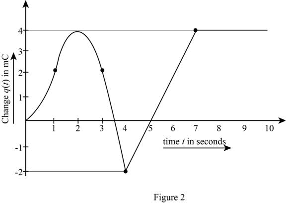
c. Sketch
(a)
The amount of current that flows through the wire for the given time.
Answer to Problem 2.9HP
The current that flows though the wire for the time interval
Explanation of Solution
Calculation:
The given time is
The conversion from
The conversion from
The conversion from
The conversion from
The given diagram is shown in Figure 1.
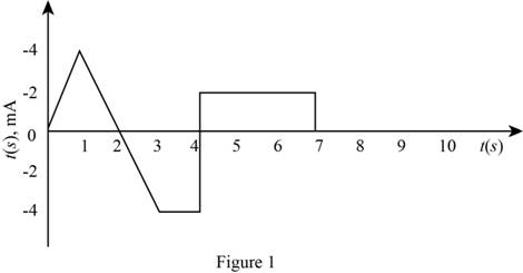
The expression for the current as a function of time is given by,
The slope of the line that represents the current from
The current for the time interval
The expression for the charge that flows through the wire for the time interval
Substitute
Conclusion:
Therefore, the charge that flows though the wire for the time interval
(b)
The charge that flows through the given time interval.
Answer to Problem 2.9HP
The charge that will flow through the wire form
Explanation of Solution
Calculation:
The given time interval is
The slope of the line that represents the current from
The conversion of
The conversion of
The conversion of
The current for the time interval
Substitute
Substitute
The expression for the charge stored from
Substitute
Substitute
Solve further as,
The expression for the charge stored from
Substitute
Substitute
Solve further as,
The mathematical expression for the straight line that represents the current waveform from
The expression for the charge stored from
Substitute
Solve further as,
The mathematical expression for the straight line that represents the current waveform from
The expression for the charge stored from
Substitute
The mathematical expression for the straight line that represents the current waveform from
The expression for the charge stored from
Substitute
The mathematical expression for the straight line that represents the current waveform from
The expression for the charge stored from
Substitute
The current is zero for
The expression for the charge stored from
Substitute
The charge stored from
Substitute
The charge stored from
Substitute
Conclusion:
Therefore, the charge that will flow through the wire form
(c)
To sketch:
The graph for
Answer to Problem 2.9HP
The sketch for
Explanation of Solution
Calculation:
The expression for the current for different time interval is given by,
The integration of the above equation with respect to time to obtain the charge expression is given by,
The evaluated form for the expression of charge for the different time interval is given by,
Substitute
Substitute
Substitute
Substitute
Substitute
Substitute
Substitute
Substitute
Substitute
Substitute
Substitute
The sketch of
The required diagram is shown in Figure 2.
Want to see more full solutions like this?
Chapter 2 Solutions
Principles and Applications of Electrical Engineering


- NEED HANDWRITTEN SOLUTION DO NOT USE AI OR CHATGPTarrow_forward2) Determine the voltage gain of the follower depicted in Fig. 2. Assume Is= 7 × 10-16. B = 100, VA = 5 V. Also assume the capacitors are very large. (40 points)arrow_forwardCalculate the voltage gain and I/O impedance of circuits shown in Fig. 1. Assume (60 points- each section 20 points) J Vina кат Vb J Vina кат VCC VCC VCC Vino - Vout - Vout Rs w Q2 Q2 (c) (b) Q2 = (a) - Voutarrow_forward
- Not use ai please letarrow_forwardUse PSpice to create the circuit and show the circuit along with simulation results. Also please explicitly answer the question (i.e. have the answer make sense and not in parts where there is no final answer.)arrow_forwardProblem 5 Plot the impulse response of the system shown below. Hint: This is done graphically with 4 convolutions. x[n] D y[n]< D D D D D D D D D D Darrow_forward
- Use PSpice to create the circuit. Also please explicitly answer whether the load line intersects the -0.7 line at the computed point.arrow_forwardIn class, we wrote on the blackboard a byte addressable memory where each element was 2 nibbles: For example: Main memory A Address Offset Data Data Data Data Data Data Data Data Data Data Data Data Data Data Data Data 0 1 2 3 4 5 6 0 Ox10 0x00 0x02 0x2B Ox4F 0x00 0x00 0x00 0x11 0x12 0x20 0x10 0x10 0x00 OxFF Ox3E DxDD 0x00 0x00 0x00 0x00 0x00 0x00 0x00 7 0x1C 0x00 8 9 A 0x00 0x00 0x01 0x00 0x00 0x01 0x00 0x00 0x01 B с D E 0x00 0x05 0x04 0x03 0x02 0x00 Ox3D 0x00 0x1C Ox2F 0x00 Ox1F OxFF 0x03 0x02 F What is the contents of address 0x1C in main memory A for a 32 bit machine using Big Endian format? What is the contents of address 0x1C in main memory A for a 16 bit machine using Little Endian format? What is the contents of the indirect address at 0x04 in main memory A for a Big Endian 32 bit machine ((0x4))? What is the contents of 4(0x10) in main memory A for a 16 bit Little Endian machine? What is the contents of the address 16(0xC) for a 64 bit Little Endian machine?arrow_forwardProblem 4 Consider the system shown below where h₁[n] = {2,1,2} and h₂[n] = (n+1) u[n] (− means subtraction). h₂[n] x [n]- h₁[n] бел-27- h₂[n] y[n] (a) Determine the impulse response of the system and plot it for n = -3,...,6. (b) Determine graphically the response of the system to the following input. x[n] 2 4 5arrow_forward
- Not use ai pleasearrow_forwardDesign a self-biased JFET circuit (Fig. 6) assuming VGS(0) = -1.3 and ipss= 20 mA. We require a VGS = -0.7. Assume a supply voltage of 15 volts. Draw the load line for this circuit using Fig. 4b once you have selected the appropriate values for the components. Does the load line intersect the VGS = -0.7 volt line at the computed in point? RD. RG Rs 12 20nA GS = -1.3 VGS 10nA Fig. 6. Circuit for Examples 2 &3. 50 100 150 200 □ ID(J1) UDS Fig. 4b. The IV characteristics of an n-channel JFET (J113). The plots are for VGs increments of 0.05 volts. VGS(0) -1.3. The yellow and blue load lines are for examples 2 &3, respectively.arrow_forwardFind the operating point and the load line of a voltage-divider JFET biasing circuit using the following parameters: VGS(0) = -1.3 and Vcc = 15 volts. Assume ipss = 20 mA, RG₁ = RG2 = 10 kn, RD = 300, and Rs = 1 kn. Use Fig. 4b for the IV characteristic of the JFET. 20nA GS=-1.3 GS 10nA- 50 100 150 200 ID(J1) UDS Fig. 4b. The IV characteristics of an n-channel JFET (J113). The plots are for VGs increments of 0.05 volts. VGS(0) -1.3. The yellow and blue load lines are for examples 2 &3, respectively.arrow_forward
 Introductory Circuit Analysis (13th Edition)Electrical EngineeringISBN:9780133923605Author:Robert L. BoylestadPublisher:PEARSON
 Delmar's Standard Textbook Of ElectricityElectrical EngineeringISBN:9781337900348Author:Stephen L. HermanPublisher:Cengage Learning
 Programmable Logic ControllersElectrical EngineeringISBN:9780073373843Author:Frank D. PetruzellaPublisher:McGraw-Hill Education
 Fundamentals of Electric CircuitsElectrical EngineeringISBN:9780078028229Author:Charles K Alexander, Matthew SadikuPublisher:McGraw-Hill Education
 Electric Circuits. (11th Edition)Electrical EngineeringISBN:9780134746968Author:James W. Nilsson, Susan RiedelPublisher:PEARSON
 Engineering ElectromagneticsElectrical EngineeringISBN:9780078028151Author:Hayt, William H. (william Hart), Jr, BUCK, John A.Publisher:Mcgraw-hill Education,