
Concept explainers
Videos
For the circuits of Figure P2.42, determine the resistor values (including the power rating) necessaryto achieve the indicated voltages. Resistors are available in
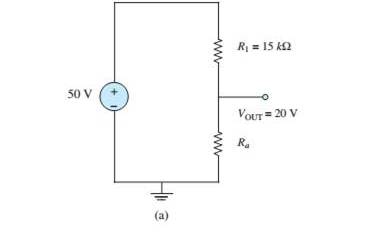
(a)
The values of the resistors which is necessary to achieve the indicated voltage.
Answer to Problem 2.42HP
The value of all the given ratings is greater than
Explanation of Solution
Calculation:
The given diagram is shown in Figure 1.
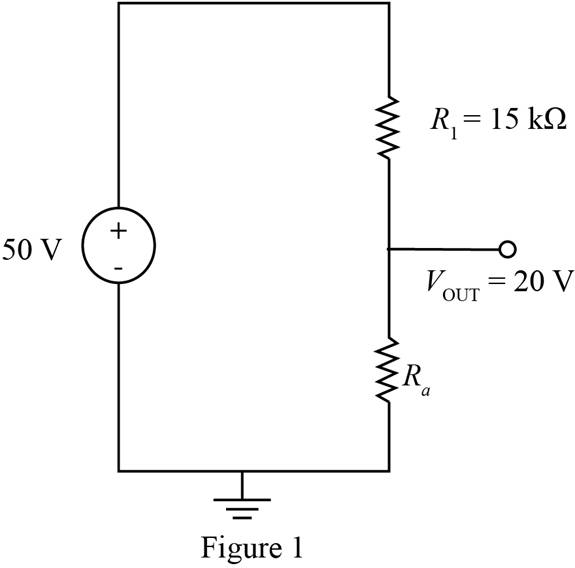
To calculate the value of the resistance
The total current in the circuit is calculated as,
The expression to calculate the power rating across the resistance
Substitute
The available ratings of the resistance are
Conclusion:
Therefore, the value of all the given ratings is greater than
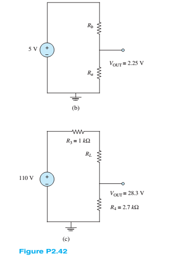
(b)
The values of the resistors which is necessary to achieve the indicated voltage.
Answer to Problem 2.42HP
The value of all the given ratings is greater than
Explanation of Solution
Calculation:
The given diagram is shown in Figure 2
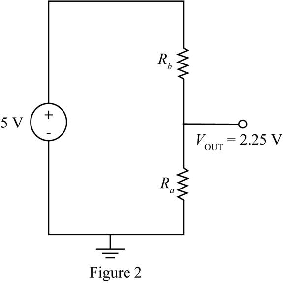
To calculate the value of the resistance
Substitute
The expression for the total current in the circuit is given by,
Substitute
The expression to calculate the power rating across the resistance
Substitute
The expression to calculate the power rating across the resistance
Substitute
The available ratings of the resistance are
Conclusion:
Therefore, the value of all the given ratings is greater than
(c)
The values of the resistors which is necessary to achieve the indicated voltage.
Answer to Problem 2.42HP
The power rating across the load must be
Explanation of Solution
Calculation:
The given diagram is shown in Figure 3.
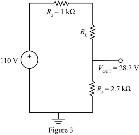
To calculate the value of the resistance
The expression for the total current in the circuit is given by,
Substitute
The expression to calculate the power rating across the resistance
Substitute
The power rating among the ratings
Conclusion:
Therefore, the power rating across the load must be
Want to see more full solutions like this?
Chapter 2 Solutions
Principles and Applications of Electrical Engineering


- feedback and open-loop gains. R2 RI =B=S Vi name the circuit, derive and find the oscillation RA Ca Rx 000arrow_forward5 Find the value of voltage Vy using nodal analysis (write and then solve the set of equations to get voltage Vx from your variables.) 43 LX + Vx да ww 1 23 дъх 83 38 wwarrow_forwardhelp on this question about block diagram reduction?arrow_forward
- 4) Find the valve of current if using nodal analys.3. (write and then solve the set of equations toget current Ex from your voltage variables.) M 3 ча + GA हुप 8Aarrow_forward2) Write but do not solve the set of Nodal equations for this circuit. 35 34 M x www 2 3A ↑ -+ 1v {7 ww 6 Bixarrow_forward3) Write: but do not solve the set of Nodal equations. for this circuit. m 4 13 35 23 ZA 5 M 8V (±) 6arrow_forward
- Feedback and open-loop gains. کا ✓ = B= S R1 ww C1 C2 R2 ww derive the oscillation frequency,arrow_forward1) Write but do not solve the set of Nodal equations for this circuit. 12 m 8 4A √3 ww www 6 ±7V 5 हुप Дам V 1 3 mmm 2Aarrow_forwardUse Gauss elimination method to find I₁, I2 and I, for the circuit shown below, if 60 12 Ω 80 13 4Ω 32V 16 Ωarrow_forward
- solve in detailarrow_forwardProblem 5 Plot the impulse response of the system shown below. Hint: This is done graphically with 4 convolutions. x[n] D y[n]< D D D D D D D D D D Darrow_forwardProblem 3 Assume that a[n] and y[n] satisfy the relation y[n] = −x[n−2]+h[n−2] * x[n+1] h[n] -3-2-10123 n where h[n] is shown in the figure. Can we equivalently write that y[n] = g[n] * x[n] for some sequence g[n] ? If so, plot g[n]. If not, explain why.arrow_forward
 Introductory Circuit Analysis (13th Edition)Electrical EngineeringISBN:9780133923605Author:Robert L. BoylestadPublisher:PEARSON
 Delmar's Standard Textbook Of ElectricityElectrical EngineeringISBN:9781337900348Author:Stephen L. HermanPublisher:Cengage Learning
 Programmable Logic ControllersElectrical EngineeringISBN:9780073373843Author:Frank D. PetruzellaPublisher:McGraw-Hill Education
 Fundamentals of Electric CircuitsElectrical EngineeringISBN:9780078028229Author:Charles K Alexander, Matthew SadikuPublisher:McGraw-Hill Education
 Electric Circuits. (11th Edition)Electrical EngineeringISBN:9780134746968Author:James W. Nilsson, Susan RiedelPublisher:PEARSON
 Engineering ElectromagneticsElectrical EngineeringISBN:9780078028151Author:Hayt, William H. (william Hart), Jr, BUCK, John A.Publisher:Mcgraw-hill Education,