
Principles and Applications of Electrical Engineering
6th Edition
ISBN: 9780073529592
Author: Giorgio Rizzoni Professor of Mechanical Engineering, James A. Kearns Dr.
Publisher: McGraw-Hill Education
expand_more
expand_more
format_list_bulleted
Videos
Textbook Question
Chapter 2, Problem 2.18HP
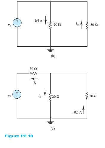
In the circuits of Figure P2.18, the directions ofcurrent and polarities of voltage have already been defined. Find the actual values of the indicated currentsand voltages.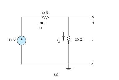
Expert Solution & Answer
Want to see the full answer?
Check out a sample textbook solution
Students have asked these similar questions
1. For v(t)=2Σn-[8(t-n) + 28(t-n-0.4)], determine
(a) (10%) a figure of v(t);
(b) (5%) period To;
(c) (10%) Fourier series in Form III;
(d) (5%) Fourier transform;
(e) (5%) total power.
5. In the figure, v(t) = m(t)ej2nfct where the message signal is m(t): = Acos (2πfmt) and the carrier signal is
vc(t) = 2e−j(2nfct+0) where 0 is constant and 0 < fm
= cos (2π x 10t+ 0) where 0 is random with a probability density
E [0, 2π), and f(0) = 0 otherwise. v,(t) passes through a linear filter below.
2. Consider a random process v(t)
function f(0) = 1/(2) for
vi(t)-
H(f)
vo(t)
Determine
(a) (5%) vo(t);
(b) (10%) autocorrelation function of v(t);
(c) (8%) power spectral density function of vo(t);
(d) (7%) power of vo(t).
1
=
H(f)
2πf2+1
Chapter 2 Solutions
Principles and Applications of Electrical Engineering
Ch. 2 - A free electron has an initial potential energy...Ch. 2 - The units for voltage, current, and resistance are...Ch. 2 - A particular fully charged battery can deliver...Ch. 2 - The charge cycle shown in Figure P2.4 is an...Ch. 2 - Batteries (e.g., lead-acid batteries) store...Ch. 2 - What determines: a. The current through an ideal...Ch. 2 - An automotive battery is rated at 120 A-h. This...Ch. 2 - A car battery kept in storage in the basement...Ch. 2 - Suppose the current through a wire is given by the...Ch. 2 - The charge cycle shown in Figure P2.10 is...
Ch. 2 - The charging scheme used in Figure P2.11 is...Ch. 2 - The charging scheme used in Figure P2.12 is...Ch. 2 - Use KCL to determine the unknown currents in the...Ch. 2 - Use KCL to find the current i1 and i2 in Figure...Ch. 2 - Use KCL to find the current i1,i2, and i3 in the...Ch. 2 - Use KVL to find the voltages v1,v2, and v3 in...Ch. 2 - Use KCL to determine the current i1,i2,i3, and i4...Ch. 2 - In the circuits of Figure P2.18, the directions...Ch. 2 - Find the power delivered by each source in Figure...Ch. 2 - Determine whether each element in Figure P2.20 is...Ch. 2 - In the circuit of Figure P2.21, determine the...Ch. 2 - For the circuit shown in Figure P2.22: a....Ch. 2 - For the circuit shown in Figure P2.23,...Ch. 2 - For the circuit shown in Figure P2.24, determine...Ch. 2 - For the circuit shown in Figure P2.25, determine...Ch. 2 - Prob. 2.26HPCh. 2 - Prob. 2.27HPCh. 2 - Prob. 2.28HPCh. 2 - Prob. 2.29HPCh. 2 - Prob. 2.30HPCh. 2 - Prob. 2.31HPCh. 2 - In the circuit of Figure P2.32, assume v2=vs/6 and...Ch. 2 - Prob. 2.33HPCh. 2 - An incandescent light bulb rated at 100 W will...Ch. 2 - An incandescent lightbulb rated at 60 W...Ch. 2 - Refer to Figure P2.36, and assume that...Ch. 2 - Refer to Figure P2.37, and assume that...Ch. 2 - Refer to Figure P2.38, and assume...Ch. 2 - Prob. 2.39HPCh. 2 - With no load attached, the voltage at the...Ch. 2 - Prob. 2.41HPCh. 2 - For the circuits of Figure P2.42, determine the...Ch. 2 - At an engineering site, a 1-hp motor is placed...Ch. 2 - Cheap resistors are fabricated by depositing a...Ch. 2 - Prob. 2.45HPCh. 2 - Use KCL and Ohm’s law to determine the current...Ch. 2 - Refer to Figure P2.13. Assume R0=1,R1=2,R2=3,R3=4...Ch. 2 - Apply KCL and Ohm’s law to find the power supplied...Ch. 2 - Refer to Figure P2.49 and assume...Ch. 2 - Refer to Figure P2.49 and assume...Ch. 2 - Prob. 2.51HPCh. 2 - The voltage divider network of Figure P2.52 is...Ch. 2 - Find the equivalent resistance seen by the source...Ch. 2 - Find the equivalent resistance seen by the source...Ch. 2 - In the circuit of Figure P2.55, the power absorbed...Ch. 2 - Find the equivalent resistance between terminals...Ch. 2 - For the circuit shown in Figure P2.57, find the...Ch. 2 - For the circuit shown in Figure P2.58,find the...Ch. 2 - Refer to Figure P2.59. Assume...Ch. 2 - Find the equivalent resistance seen by the source...Ch. 2 - For the circuit shown in Figure P2.61. assume...Ch. 2 - Determine the equivalent resistance of the...Ch. 2 - For the circuit shown in Figure P2.58, assume...Ch. 2 - In the circuit of Figure P2.64, find the...Ch. 2 - Refer to Figure P2.64 and determine the equivalent...Ch. 2 - Find the equivalent resistance seen by the source...Ch. 2 - Determine the voltage vo between nodes A and Bin...Ch. 2 - Refer to Figure P2.68 and assume...Ch. 2 - Prob. 2.69HPCh. 2 - Prob. 2.70HPCh. 2 - Prob. 2.71HPCh. 2 - The circuit of Figure P2.72 is used to measure the...Ch. 2 - Consider the practical ammeter, depicted in Figure...Ch. 2 - Prob. 2.74HPCh. 2 - Prob. 2.75HPCh. 2 - Prob. 2.76HPCh. 2 - A voltmeter is used to determine the voltage...Ch. 2 - Prob. 2.78HPCh. 2 - Figure P2.79 shows an aluminum cantilevered beam...Ch. 2 - Refer to Figure P2.79 but assume that the...
Knowledge Booster


Learn more about
Need a deep-dive on the concept behind this application? Look no further. Learn more about this topic, electrical-engineering and related others by exploring similar questions and additional content below.Similar questions
- 4. Consider v(t) = 2 cos(t) + 5 sin(2t) passes through a linear system with frequence response H(f). 3 vi(t) Determine (a) (10%) vo(t); (b) (5%) power of vo(t). H(f) → vo(t) H(f)= 3, Ifls- 4π (0, otherwise.arrow_forward3. For the AM demodulator in figure, v(t) = m(t)cos (2πfet + 4) with a constant where the message signal is m(t) v(t)- =Acos (2πfmt) and carrier signal is v(t) = cos (2πfet) with fmarrow_forwardNot use ai pleasearrow_forward14arrow_forward5. In the figure, v(t) = m(t)ej2nfct where the message signal is m(t): = Acos (2πfmt) and the carrier signal is vc(t) = 2e−j(2nfct+0) where 0 is constant and 0 < fmarrow_forwardFor the following parallel resonant bandpass filter, find the exact center frequency of the pass band and the bandwidth. Given: • Vin = 20 V • L = 7.5 μH C = 270 pF - Rw = 5.1 Q R₁ = 750 0 Center Frequency: f= kHz Bandwidth: BW= kHz Maximum Output Voltage: Vout(max)= V Minimum Output Voltage: Vout(min) = V 270 pF HH C ww L Rw 5.1Q 7.5 HH Vin 20 V RLoad 750 Ω Voutarrow_forward3. For v(t) = 4Σn=-8(t-n- 0.5), (a) (10%) draw a figure of v(t); (b) (5%) determine period To; (c) (10%) determine Fourier transform form III; (d) (5%) determine power spectral density.arrow_forward1. For v(t) = 2 cos(2π x 20t) + 3 sin (2π x 10t), determine (a) (5%) period To; →→T= (b) (8%) Fourier transform form II; (c) (5%) power of the fundamental frequency component; (d) (2%) total power. s [ue] dtarrow_forwardDesign, simulate and implement an electropneumatic automation system with PLC for 2 cylinders (A and B), which when pressing the push button S1 performs the following pneumatic sequence: A- B- B+ A+ for 10 seconds. With the push button S2 the sequence can be stopped at any time.arrow_forward4. Consider v(t) = 2 cos(t) + 5 sin(2t) passes through a linear system with frequence response H(f). 3 vi(t) Determine (a) (10%) vo(t); (b) (5%) power of vo(t). H(f) → vo(t) H(f)= 3, Ifls- 4π (0, otherwise.arrow_forward2. (10%) In a 6G wireless communication system, the antenna length is L = 0.5 cm. Determine the carrier frequency fc according to the antenna length.arrow_forwardHANDWRITTEN SOLUTION REUIRED NOT USING CHATGPTarrow_forwardarrow_back_iosSEE MORE QUESTIONSarrow_forward_iosRecommended textbooks for you
 Power System Analysis and Design (MindTap Course ...Electrical EngineeringISBN:9781305632134Author:J. Duncan Glover, Thomas Overbye, Mulukutla S. SarmaPublisher:Cengage Learning
Power System Analysis and Design (MindTap Course ...Electrical EngineeringISBN:9781305632134Author:J. Duncan Glover, Thomas Overbye, Mulukutla S. SarmaPublisher:Cengage Learning
02 - Sinusoidal AC Voltage Sources in Circuits, Part 1; Author: Math and Science;https://www.youtube.com/watch?v=8zMiIHVMfaw;License: Standard Youtube License