
Videos
(a)
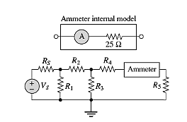
The currentthroughR5 with and without ammeter for the given valuesof the resistor.
Answer to Problem 2.78HP
The current through resistor:
With meter in circuit:
Without meter in circuit:
Explanation of Solution
Given information:
The given circuit is shown below.

Also,
Calculation:
First, find an expression for the current through
And
Therefore,
Hence for given values of R5
The current through resistor:
With meter in circuit,
Without meter in circuit,
(b)
The current through R5 with and without ammeter for the given values of the resistor.
Answer to Problem 2.78HP
The current through resistor:
With meter in circuit:
Without meter in circuit:
Explanation of Solution
Given information:
The given circuit is shown below.

Also,
Calculation:
First, find an expression for the current through
And
Therefore,
Hence for given values of R5
The current through resistor:
With meter in circuit,
Without meter in circuit,
(c)
The current through R5 with and without ammeter for the given values of the resistor.
Answer to Problem 2.78HP
The current through resistor:
With meter in circuit:
Without meter in circuit:
Explanation of Solution
Given information:
The given circuit is shown below.
Also,
Calculation:
First, find an expression for the current through
And
Therefore,
Hence for given values of R5
The current through resistor:
With meter in circuit,
Without meter in circuit,
(d)
The current through R5 with and without ammeter for the given values of the resistor.
Answer to Problem 2.78HP
The current through resistor:
With meter in circuit:
Without meter in circuit:
Explanation of Solution
Given information:
The given circuit is shown below.

Also,
Calculation:
First, find an expression for the current through
And
Therefore,
Hence for given values of R5
The current through resistor:
With meter in circuit,
Without meter in circuit,
Want to see more full solutions like this?
Chapter 2 Solutions
Principles and Applications of Electrical Engineering


- 1. For v(t)=2Σn-[8(t-n) + 28(t-n-0.4)], determine (a) (10%) a figure of v(t); (b) (5%) period To; (c) (10%) Fourier series in Form III; (d) (5%) Fourier transform; (e) (5%) total power.arrow_forward5. In the figure, v(t) = m(t)ej2nfct where the message signal is m(t): = Acos (2πfmt) and the carrier signal is vc(t) = 2e−j(2nfct+0) where 0 is constant and 0 < fmarrow_forward= cos (2π x 10t+ 0) where 0 is random with a probability density E [0, 2π), and f(0) = 0 otherwise. v,(t) passes through a linear filter below. 2. Consider a random process v(t) function f(0) = 1/(2) for vi(t)- H(f) vo(t) Determine (a) (5%) vo(t); (b) (10%) autocorrelation function of v(t); (c) (8%) power spectral density function of vo(t); (d) (7%) power of vo(t). 1 = H(f) 2πf2+1arrow_forward4. Consider v(t) = 2 cos(t) + 5 sin(2t) passes through a linear system with frequence response H(f). 3 vi(t) Determine (a) (10%) vo(t); (b) (5%) power of vo(t). H(f) → vo(t) H(f)= 3, Ifls- 4π (0, otherwise.arrow_forward3. For the AM demodulator in figure, v(t) = m(t)cos (2πfet + 4) with a constant where the message signal is m(t) v(t)- =Acos (2πfmt) and carrier signal is v(t) = cos (2πfet) with fmarrow_forwardNot use ai pleasearrow_forward14arrow_forward5. In the figure, v(t) = m(t)ej2nfct where the message signal is m(t): = Acos (2πfmt) and the carrier signal is vc(t) = 2e−j(2nfct+0) where 0 is constant and 0 < fmarrow_forwardFor the following parallel resonant bandpass filter, find the exact center frequency of the pass band and the bandwidth. Given: • Vin = 20 V • L = 7.5 μH C = 270 pF - Rw = 5.1 Q R₁ = 750 0 Center Frequency: f= kHz Bandwidth: BW= kHz Maximum Output Voltage: Vout(max)= V Minimum Output Voltage: Vout(min) = V 270 pF HH C ww L Rw 5.1Q 7.5 HH Vin 20 V RLoad 750 Ω Voutarrow_forward3. For v(t) = 4Σn=-8(t-n- 0.5), (a) (10%) draw a figure of v(t); (b) (5%) determine period To; (c) (10%) determine Fourier transform form III; (d) (5%) determine power spectral density.arrow_forward1. For v(t) = 2 cos(2π x 20t) + 3 sin (2π x 10t), determine (a) (5%) period To; →→T= (b) (8%) Fourier transform form II; (c) (5%) power of the fundamental frequency component; (d) (2%) total power. s [ue] dtarrow_forwardDesign, simulate and implement an electropneumatic automation system with PLC for 2 cylinders (A and B), which when pressing the push button S1 performs the following pneumatic sequence: A- B- B+ A+ for 10 seconds. With the push button S2 the sequence can be stopped at any time.arrow_forwardarrow_back_iosSEE MORE QUESTIONSarrow_forward_iosRecommended textbooks for you
 Introductory Circuit Analysis (13th Edition)Electrical EngineeringISBN:9780133923605Author:Robert L. BoylestadPublisher:PEARSON
 Delmar's Standard Textbook Of ElectricityElectrical EngineeringISBN:9781337900348Author:Stephen L. HermanPublisher:Cengage Learning
 Programmable Logic ControllersElectrical EngineeringISBN:9780073373843Author:Frank D. PetruzellaPublisher:McGraw-Hill Education
 Fundamentals of Electric CircuitsElectrical EngineeringISBN:9780078028229Author:Charles K Alexander, Matthew SadikuPublisher:McGraw-Hill Education
 Electric Circuits. (11th Edition)Electrical EngineeringISBN:9780134746968Author:James W. Nilsson, Susan RiedelPublisher:PEARSON
 Engineering ElectromagneticsElectrical EngineeringISBN:9780078028151Author:Hayt, William H. (william Hart), Jr, BUCK, John A.Publisher:Mcgraw-hill Education,
Introductory Circuit Analysis (13th Edition)Electrical EngineeringISBN:9780133923605Author:Robert L. BoylestadPublisher:PEARSONDelmar's Standard Textbook Of ElectricityElectrical EngineeringISBN:9781337900348Author:Stephen L. HermanPublisher:Cengage LearningProgrammable Logic ControllersElectrical EngineeringISBN:9780073373843Author:Frank D. PetruzellaPublisher:McGraw-Hill EducationFundamentals of Electric CircuitsElectrical EngineeringISBN:9780078028229Author:Charles K Alexander, Matthew SadikuPublisher:McGraw-Hill EducationElectric Circuits. (11th Edition)Electrical EngineeringISBN:9780134746968Author:James W. Nilsson, Susan RiedelPublisher:PEARSONEngineering ElectromagneticsElectrical EngineeringISBN:9780078028151Author:Hayt, William H. (william Hart), Jr, BUCK, John A.Publisher:Mcgraw-hill Education,Lesson 2 - Source Transformations, Part 2 (Engineering Circuits); Author: Math and Science;https://www.youtube.com/watch?v=7gno74RhVGQ;License: Standard Youtube License