
Concept explainers
Videos
(a)
The total power dissipated by the ideal source.
Answer to Problem 2.31HP
The power delivered for the current of
Explanation of Solution
Calculation:
The formula for the total power supplied or delivered by the ideal voltage source is given by,
Substitute
Substitute
Substitute
Substitute
Substitute
Substitute
Substitute
Conclusion:
Therefore, the power delivered for the current of
(b)
The power dissipated within the non ideal source.
Answer to Problem 2.31HP
The power dissipated by the resistance of
Explanation of Solution
Calculation:
The formula for the power delivered by the non ideal power source is given by,
Substitute
Substitute
Substitute
Substitute
Substitute
Substitute
Conclusion:
Therefore, the power dissipated by the resistance of
(c)
The amount of power supplied by the load resistor.
Answer to Problem 2.31HP
The power supplied to the load resistance of
Explanation of Solution
Calculation:
The given diagram is shown in Figure 1
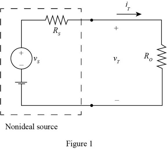
Apply KCL to the above circuit.
The formula for the load power is given by,
The conversion of
The conversion of
The conversion of
The conversion of
The conversion of
The conversion of
Substitute
Substitute
Substitute
Substitute
Substitute
Substitute
Substitute
Substitute
Substitute
Substitute
Substitute
Substitute
Conclusion:
Therefore, the power supplied to the load resistance of
(d)
The terminal voltage
Answer to Problem 2.31HP
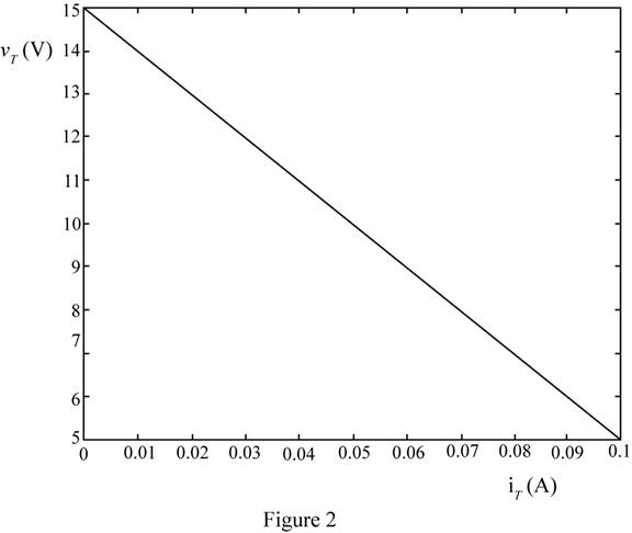
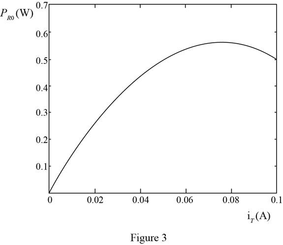
The plot between the terminal voltage and the load current is shown in Figure 2 and plot for the load current and power delivered to the load is shown in Figure 3
Explanation of Solution
Calculation:
The plot for the terminal voltage and total current is shown in Figure 2.
The plot between for the power delivered to the load versus the total current is shown in Figure 3
Conclusion:
Therefore, the plot between the terminal voltage and the load current is shown in Figure 2 and plot for the load current and power delivered to the load is shown in Figure 3
Want to see more full solutions like this?
Chapter 2 Solutions
Principles and Applications of Electrical Engineering


- The magnetic circuit shown in the figure is made of TRAN-COR material, the flow magnetic power on the right arm (BCDE) is 6 x 10 -4 Wb. (disregard marginal effects anddispersion) Calculate the current in the 200-turn coilarrow_forwardtheoretically and compare it with the test value. Report :- 1- Calculate the D.C. output Voltagearrow_forwardf 2- For resistive load, measured the output voltage by using oscilloscope, then sketch this wave.. 3- Measure the average values of Vɩ and Iɩ . 4- Repeat steps 2 & 3 but for R.L load.arrow_forward
- A single-phase 10 kVA, 1000/100V transformer has the relative voltage parameters of: εrcc = 6%, εxcc = 8%, core losses Pfe = 200W and nominal copper losses of Pcu = 300W.A load of 2 < 30° Ω is connected to the secondary of the transformer. Determine using pu ́s calculations:to. The voltage in the primary, if the voltage of the secondary (at load) is 100 V.b. If the voltage in the primary remains constant at 1000 V, what would be the voltage at the load?c. The voltage regulation of the transformer under the conditions b.d. The efficiency of the transformer under the conditions b.arrow_forward9.38 For the op-amp circuit of Fig. P9.38:(a) Obtain an expression for H(w) = Vo/Vs in standard form.(b) Generate spectral plots for the magnitude and phase ofH(w), given that R1 = 99 kW, R2 = 1 kW, and C = 0.1 μF.(c) What type of filter is it? What is its maximum gain?arrow_forwardA short 3-o transmission line with an impedance of (6+j 8)2 per phase has receiving end of 22000 kw, 120 KV, 0.8 lagging p.f. Determine (i) Sending voltage (ii) Sending current (iii) Sending power factor (iv) voltage regulation.arrow_forward
- 9.37 For the op-amp circuit of Fig. P9.37:*(a) Obtain an expression for H(w) = Vo/Vs in standard form.(b) Generate spectral plots for the magnitude and phase ofH(w), given that R1 = 1 kW, R2 = 4 kW, and C = 1 μF.(c) What type of filter is it? What is its maximum gainarrow_forwardI need a detailed drawing with explanation Solve es 4 = -20125 شكا +981X914 pv + 96852 الإنجليزية (second order differential I need an example on the subject the partition method and the Laplace method. Suggest an easy equations) and you solve it using and simple example for me and solve it using two methods, only one example. 750 01 95Parrow_forwardNot use ai pleasearrow_forward
- し الإنجليزية (second order differential I need an example on the subject the partition method and the equations) and you solve it using Laplace method. Suggest an easy and simple example for me and solve it using two methods, only one example. الله X 9.01 P+96erarrow_forwardI need an example on the subject (second order differential equations) and you solve it using the partition method and the Laplace method. Suggest an easy and simple example for me and solve it using two methods, only one example.arrow_forward5- Discuss your resultsarrow_forward
 Introductory Circuit Analysis (13th Edition)Electrical EngineeringISBN:9780133923605Author:Robert L. BoylestadPublisher:PEARSON
 Delmar's Standard Textbook Of ElectricityElectrical EngineeringISBN:9781337900348Author:Stephen L. HermanPublisher:Cengage Learning
 Programmable Logic ControllersElectrical EngineeringISBN:9780073373843Author:Frank D. PetruzellaPublisher:McGraw-Hill Education
 Fundamentals of Electric CircuitsElectrical EngineeringISBN:9780078028229Author:Charles K Alexander, Matthew SadikuPublisher:McGraw-Hill Education
 Electric Circuits. (11th Edition)Electrical EngineeringISBN:9780134746968Author:James W. Nilsson, Susan RiedelPublisher:PEARSON
 Engineering ElectromagneticsElectrical EngineeringISBN:9780078028151Author:Hayt, William H. (william Hart), Jr, BUCK, John A.Publisher:Mcgraw-hill Education,