Concept explainers
Videos
(a)
The time required to reduce theangular velocityof cylinder A to
Cylinder A has the angular velocity of
Answer to Problem 17.75P
Time required for cylinder A to attain
Explanation of Solution
Given:
Mass of cylinder,
Radius of cylinder,
Angular velocity of cylinder
Concept used:
Impulse momentum principle.
Moment of inertia
Calculation:
According to impulse-momentum principle for cylinder B,
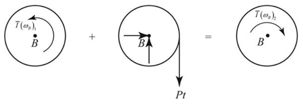
Taking moment about B,
We have,
Moment of inertia,
As per kinematics.
Considering C as aninstantenous center of cylinder A.
According to the impulse-momentum principle in cylinder A,
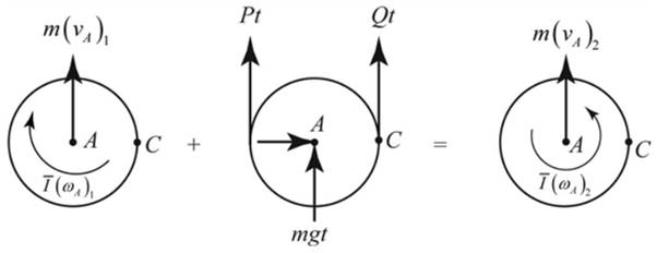
Taking moment about C,
Conclusion:
Thus we can find the time required to reduce angular velocity from
(b)
The tension in the portion of the belt connecting the two cylinders.
Answer to Problem 17.75P
Belt tension between two cylinders is
Explanation of Solution
Given:
The radius of the cylinder,
Angular velocity of cylinder
Concept used:
Impulse momentum principle
Moment of inertia
Calculation:
As per calculation is done in subpart (a),
We have,
Conclusion:
Thus the tension in belt between cylinder A and B is found to be
Want to see more full solutions like this?
Chapter 17 Solutions
VECTOR MECH...,DYNAMICS(LOOSE)-W/ACCESS


- a 300n girl and an 400n boy stand on a 16m platform supported by posts A and B. The platform itself weighs 200N. What are the forces exerted by the supports on the platform?arrow_forwardC A cylindrical piece of steel 38 mm (1½ in.) in diameter is to be quenched in moderately agi- tated oil. Surface and center hardnesses must be at least 50 and 40 HRC, respectively. Which of the following alloys satisfy these requirements: 1040, 5140, 4340, 4140, and 8640? Justify your choice(s).arrow_forwardUsing the isothermal transformation diagram for a 1.13 wt% C steel alloy (Figure 10.39), determine the final microstructure (in terms of just the microconstituents present) of a small specimen that has been subjected to the following time-temperature treatments. In each case assume that the specimen begins at 920°C (1690°F) and that it has been held at this temperature long enough to have achieved a complete and homogeneous austenitic structure. (a) Rapidly cool to 250°C (480°F), hold for 103 s, then quench to room temperature. (b) Rapidly cool to 775°C (1430°F), hold for 500 s, then quench to room temperature. (c) Rapidly cool to 400°C (750°F), hold for 500 s, then quench to room temperature. (d) Rapidly cool to 700°C (1290°F), hold at this temperature for 105 s, then quench to room temperature. (e) Rapidly cool to 650°C (1200°F), hold at this temperature for 3 s, rapidly cool to 400°C (750°F), hold for 25 s, then quench to room temperature. (f) Rapidly cool to 350°C (660°F), hold for…arrow_forward
- How to solve this?arrow_forwardA start-up company wants to convert an ICE vehicle into an electric vehicle with the following specification. Power: 250 (HP) horsepower, (note: 1HP = 745 W) Range: 300-miles Fuel economy: 33.5 kilometers per gallon of gasoline. Efficiency of the ICE: 25% Energy Conversion: One gallon of gasoline at 100% efficiency is equal to 33.5 kWh/gallon). a)Calculate the EV consumption rate as Wh/km and find the total energy of the battery pack in KWh to replace the internal combustion engine. b)Design an 8-module battery pack for this full electric vehicle without compromising its range and performance (power). Use commercially available cylindrical cells lithium cell with 20Ah capacity and 3.125 V average voltage. Cell dimensions are 5cm diameter and 10 cm height. The electric motor requires 250 V input that will be provided directly from the battery pack, Report the configuration of each module in…arrow_forward"11-17 The shaft shown in Figure P11-3 was designed in Problem 10-17. For the data in the row(s) assigned from Table P11-1, and the corresponding diameter of shaft found in Problem 10-17, design suitable bearings to support the load for at least 1E8 cycles at 1800 rpm. State all assumptions. (a) Using hydrodynamically lubricated bronze sleeve bearings with Ox = 15, 11d=0.75, and a clearance ratio of 0.001. ✓ ✓ cast-iron roller FIGURE P11-3 Shaft Design for Problems 11-17 b gear key assume bearings act as simple supports 11-19 The shaft shown in Figure P11-4 was designed in Problem 10-19. For the data in the row(s) assigned from Table P11-1, and the corresponding diameter of shaft found in Problem 10-19, design suitable bearings to support the load for at least 5E8 cycles at 1200 rpm. State all assumptions. (a) Using hydrodynamically lubricated bronze sleeve bearings with Oy = 40, 1/d=0.80, and a clearance ratio of 0.002 5. gear gear key FIGURE P11-4 Shaft Design for Problems 11-19 and…arrow_forward
- For the frame below calculate the bending moment at point R. Take P=40 and note that this value is used for both the loads and the lengths of the members of the frame. 2.5P- A Q B R С 45 degrees ✗ ✗ P i 19 Кур -2P- 4PRN -P- -arrow_forwardCalculate the bending moment at the point D on the beam below. Take F=79 and remember that this quantity is to be used to calculate both forces and lengths. 15F 30F A сarrow_forwardShow work on how to obtain P2 and T2. If using any table, please refer to it. If applying interpolation method, please show the work.arrow_forwardcast-iron roller FIGURE P11-3 Shaft Design for Problems 11-17 Chapter 11 BEARINGS AND LUBRICATION 677 gear key P assume bearings act as simple supports 11-18 Problem 7-18 determined the half-width of the contact patch for a 1.575-in-dia steel cylinder, 9.843 in long, rolled against a flat aluminum plate with 900 lb of force to be 0.0064 in. If the cylinder rolls at 800 rpm, determine its lubrication condition with ISO VG 1000 oil at 200°F. R₁ = 64 μin (cylinder); R₁ = 32 μin (plate). 11-19 The shaft shown in Figure P11-4 was designed in Problem 10-19. For the data in the row(s) assigned from Table P11-1, and the corresponding diameter of shaft found in Problem 10-19, design suitable bearings to support the load for at least 5E8 cycles at 1200 rpm. State all assumptions. (a) (b) Using hydrodynamically lubricated bronze sleeve bearings with ON = 40, 1/ d=0.80, and a clearance ratio of 0.002 5. Using deep-groove ball bearings for a 10% failure rate. *11-20 Problem 7-20 determined the…arrow_forwardCalculate the shear force at the point D on the beam below. Take F=19 and remember that this quantity is to be used to calculate both forces and lengths. 15F A сarrow_forward"II-1 The shaft shown in Figure P11-I was designed in Problem 10-1. For the data in the row(s) assigned from Table P11-1, and the corresponding diameter of shaft found in Problem 10-1, design suitable bearings to support the load for at least 7E7 cycles at 1500 rpm. State all assumptions. (a) Using hydrodynamically lubricated bronze sleeve bearings with Ox = 20, 1/d=1.25, and a clearance ratio of 0.001 5. assume bearings act as simple supports FIGURE P11-1 Shaft Design for Problem 11-1 11-2 The shaft shown in Figure P11-2 was designed in Problem 10-2. For the data in the row(s) assigned from Table P11-1, and the corresponding diameter of shaft found in Problem 10-2, design suitable bearings to support the load for at least 3E8 cycles at 2.500 rpm. State all assumptions. (a) Using hydrodynamically lubricated bronze sleeve bearings with ON=30, 1/d=1.0, and a clearance ratio of 0.002. FIGURE P11-2 Shaft Design for Problem 11-2 Table P11-1 Data for Problems assume bearings act as simple…arrow_forwardarrow_back_iosSEE MORE QUESTIONSarrow_forward_iosRecommended textbooks for you
 Elements Of ElectromagneticsMechanical EngineeringISBN:9780190698614Author:Sadiku, Matthew N. O.Publisher:Oxford University Press
 Mechanics of Materials (10th Edition)Mechanical EngineeringISBN:9780134319650Author:Russell C. HibbelerPublisher:PEARSON
 Thermodynamics: An Engineering ApproachMechanical EngineeringISBN:9781259822674Author:Yunus A. Cengel Dr., Michael A. BolesPublisher:McGraw-Hill Education
 Control Systems EngineeringMechanical EngineeringISBN:9781118170519Author:Norman S. NisePublisher:WILEY
 Mechanics of Materials (MindTap Course List)Mechanical EngineeringISBN:9781337093347Author:Barry J. Goodno, James M. GerePublisher:Cengage Learning
 Engineering Mechanics: StaticsMechanical EngineeringISBN:9781118807330Author:James L. Meriam, L. G. Kraige, J. N. BoltonPublisher:WILEY
Elements Of ElectromagneticsMechanical EngineeringISBN:9780190698614Author:Sadiku, Matthew N. O.Publisher:Oxford University PressMechanics of Materials (10th Edition)Mechanical EngineeringISBN:9780134319650Author:Russell C. HibbelerPublisher:PEARSONThermodynamics: An Engineering ApproachMechanical EngineeringISBN:9781259822674Author:Yunus A. Cengel Dr., Michael A. BolesPublisher:McGraw-Hill EducationControl Systems EngineeringMechanical EngineeringISBN:9781118170519Author:Norman S. NisePublisher:WILEYMechanics of Materials (MindTap Course List)Mechanical EngineeringISBN:9781337093347Author:Barry J. Goodno, James M. GerePublisher:Cengage LearningEngineering Mechanics: StaticsMechanical EngineeringISBN:9781118807330Author:James L. Meriam, L. G. Kraige, J. N. BoltonPublisher:WILEY