VECTOR MECH...,DYNAMICS(LOOSE)-W/ACCESS
12th Edition
ISBN: 9781260265521
Author: BEER
Publisher: MCG
expand_more
expand_more
format_list_bulleted
Concept explainers
Videos
Textbook Question
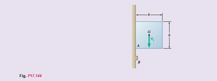
Chapter 17, Problem 17.144RP
A square block of mass m is falling with a velocity
Expert Solution & Answer
Want to see the full answer?
Check out a sample textbook solution
Students have asked these similar questions
3 kN
3 kN
1.8 kN/m
80 mm
B
300 mm
D
an
1.5 m-1.5 m--1.5 m-
PROBLEM 5.47
Using the method of Sec. 5.2, solve Prob. 5.16
PROBLEM 5.16 For the beam and loading shown, determine the
maximum normal stress due to bending on a transverse section at C.
300 mm
3 kN
3 kN
450 N-m
D
E
200 mm
300 mm
PROBLEM 5.12
Draw the shear and bending-moment diagrams for the beam and loading
shown, and determine the maximum absolute value (a) of the shear,
(b) of the bending moment.
CORRECT AND DETAILED SOLUTION WITH FBD ONLY. I WILL UPVOTE THANK YOU. CORRECT ANSWER IS ALREADY PROVIDED. I REALLY NEED FBD.
The cantilevered spandrel beam shown whose depth tapers from d1 to d2, has a constant width of 120mm. It carries a triangularly distributed end reaction.Given: d1 = 600 mm, d2 = 120 mm, L = 1 m, w = 100 kN/m1. Calculate the maximum flexural stress at the support, in kN-m.2. Determine the distance (m), from the free end, of the section with maximum flexural stress.3. Determine the maximum flexural stress in the beam, in MPa.ANSWERS: (1) 4.630 MPa; (2) 905.8688 m; (3) 4.65 MPa
Chapter 17 Solutions
VECTOR MECH...,DYNAMICS(LOOSE)-W/ACCESS
Ch. 17.1 - A round object of mass m and radius r is released...Ch. 17.1 - Prob. 17.CQ2PCh. 17.1 - Prob. 17.CQ3PCh. 17.1 - Prob. 17.CQ4PCh. 17.1 - Slender bar A is rigidly connected to a massless...Ch. 17.1 - A 200-kg flywheel is at rest when a constant 300 N...Ch. 17.1 - The rotor of an electric motor has an angular...Ch. 17.1 - Two uniform disks of the same material are...Ch. 17.1 - Two disks of the same material are attached to a...Ch. 17.1 - Prob. 17.5P
Ch. 17.1 - Prob. 17.6PCh. 17.1 - Prob. 17.7PCh. 17.1 - Prob. 17.8PCh. 17.1 - Prob. 17.9PCh. 17.1 - Prob. 17.10PCh. 17.1 - Each of the gears A and B has a mass of 10 kg and...Ch. 17.1 - Solve Prob. 17.11, assuming that the 6 N m couple...Ch. 17.1 - The gear train shown consists of four gears of the...Ch. 17.1 - Prob. 17.14PCh. 17.1 - Prob. 17.15PCh. 17.1 - Prob. 17.16PCh. 17.1 - The 15-kg rear hatch of a vehicle opens as shown...Ch. 17.1 - A slender 9-lb rod can rotate in a vertical plane...Ch. 17.1 - Prob. 17.19PCh. 17.1 - Prob. 17.20PCh. 17.1 - A collar with a mass of 1 kg is rigidly attached...Ch. 17.1 - Prob. 17.22PCh. 17.1 - Prob. 17.23PCh. 17.1 - The 30-kg turbine disk has a centroidal radius of...Ch. 17.1 - A 100-kg solid cylindrical disk, 800 mm in...Ch. 17.1 - Prob. 17.26PCh. 17.1 - Prob. 17.27PCh. 17.1 - Prob. 17.28PCh. 17.1 - Prob. 17.29PCh. 17.1 - A half-cylinder with mass m and radius r is...Ch. 17.1 - Prob. 17.31PCh. 17.1 - Two uniform cylinders, each of weight W=14 lb and...Ch. 17.1 - Two uniform cylinders, each of weight W=14 lb and...Ch. 17.1 - A bar of mass m=5 kg is held as shown between four...Ch. 17.1 - The 1.5-kg uniform slender bar AB is connected to...Ch. 17.1 - Prob. 17.36PCh. 17.1 - A 5-m-long ladder has a mass of 15 kg and is...Ch. 17.1 - Prob. 17.38PCh. 17.1 - Prob. 17.39PCh. 17.1 - The mechanism shown is one of two identical...Ch. 17.1 - The mechanism shown is one of two identical...Ch. 17.1 - Each of the two rods shown is of length L=1 m and...Ch. 17.1 - The 4-kg rod AB is attached to a collar of...Ch. 17.1 - If in Prob. 17.43 the angular velocity of the...Ch. 17.1 - The uniform rods AB and BC are of mass 3 kg and 8...Ch. 17.1 - The uniform rods AB and BC weigh 2.4 kg and 4 kg,...Ch. 17.1 - The 80-mm-radius gear shown has a mass of 5 kg and...Ch. 17.1 - Prob. 17.48PCh. 17.1 - Three shafts and four gears are used to form a...Ch. 17.1 - Prob. 17.50PCh. 17.1 - The drive belt on a vintage sander transmits 12 hp...Ch. 17.2 - Slender bar A is rigidly connected to a massless...Ch. 17.2 - A 1-m-long uniform slender bar AB has an angular...Ch. 17.2 - The 350-kg flywheel of a small hoisting engine has...Ch. 17.2 - A sphere of radius r and mass m is placed on a...Ch. 17.2 - Prob. 17.F3PCh. 17.2 - Prob. 17.52PCh. 17.2 - Prob. 17.53PCh. 17.2 - Prob. 17.54PCh. 17.2 - Prob. 17.55PCh. 17.2 - Prob. 17.56PCh. 17.2 - A disk of constant thickness, initially at rest,...Ch. 17.2 - Prob. 17.58PCh. 17.2 - A cylinder of radius r and weight W with an...Ch. 17.2 - Each of the double pulleys shown has a centroidal...Ch. 17.2 - Prob. 17.61PCh. 17.2 - Prob. 17.62PCh. 17.2 - Prob. 17.63PCh. 17.2 - A tape moves over the two drums shown. Drum A...Ch. 17.2 - Prob. 17.65PCh. 17.2 - Prob. 17.66PCh. 17.2 - Prob. 17.67PCh. 17.2 - Consider a rigid body initially at rest and...Ch. 17.2 - Prob. 17.69PCh. 17.2 - Prob. 17.70PCh. 17.2 - Prob. 17.71PCh. 17.2 - Prob. 17.72PCh. 17.2 - Prob. 17.73PCh. 17.2 - Prob. 17.74PCh. 17.2 - Prob. 17.75PCh. 17.2 - Prob. 17.76PCh. 17.2 - A sphere of radius r and mass m is projected along...Ch. 17.2 - Prob. 17.78PCh. 17.2 - Prob. 17.79PCh. 17.2 - Prob. 17.80PCh. 17.2 - Two 10-lb disks and a small motor are mounted on a...Ch. 17.2 - Prob. 17.82PCh. 17.2 - A 1.6-kg tube AB can slide freely on rod DE, which...Ch. 17.2 - In the helicopter shown, a vertical tail propeller...Ch. 17.2 - Prob. 17.85PCh. 17.2 - The 4-kg uniform disk B is attached to the shaft...Ch. 17.2 - Prob. 17.87PCh. 17.2 - Prob. 17.88PCh. 17.2 - Prob. 17.89PCh. 17.2 - Prob. 17.90PCh. 17.2 - Prob. 17.91PCh. 17.2 - Prob. 17.92PCh. 17.2 - Prob. 17.93PCh. 17.2 - Prob. 17.94PCh. 17.2 - Prob. 17.95PCh. 17.3 - A uniform slender rod AB ofmass m is at rest on a...Ch. 17.3 - Prob. 17.F5PCh. 17.3 - Prob. 17.F6PCh. 17.3 - Prob. 17.96PCh. 17.3 - A bullet weighing 0.08 lb is fired with a...Ch. 17.3 - Prob. 17.98PCh. 17.3 - Prob. 17.99PCh. 17.3 - Prob. 17.100PCh. 17.3 - Prob. 17.101PCh. 17.3 - A 45-g bullet is fired with a velocity of 400 m/s...Ch. 17.3 - Prob. 17.103PCh. 17.3 - Prob. 17.104PCh. 17.3 - A uniform slender rod AB of mass m is at rest on a...Ch. 17.3 - Prob. 17.106PCh. 17.3 - Prob. 17.107PCh. 17.3 - Prob. 17.108PCh. 17.3 - Determine the height h at which the bullet of...Ch. 17.3 - A uniform slender bar of length L=200 mm and mass...Ch. 17.3 - A uniform slender rod of length L is dropped onto...Ch. 17.3 - A uniform slender rod AB has a mass m, a length L,...Ch. 17.3 - Prob. 17.113PCh. 17.3 - The trapeze/lanyard air drop (t/LAD) launch is a...Ch. 17.3 - The uniform rectangular block shown is moving...Ch. 17.3 - The 40-kg gymnast drops from her maximum height of...Ch. 17.3 - Prob. 17.117PCh. 17.3 - A uniformly loaded square crate is released from...Ch. 17.3 - A 1-oz bullet is fired with a horizontal velocity...Ch. 17.3 - For the beam of Prob. 17.119, determine the...Ch. 17.3 - The plank CDEhas a mass of 15 kg and rests on a...Ch. 17.3 - Prob. 17.122PCh. 17.3 - A slender rod AB is released from rest in the...Ch. 17.3 - A slender rod AB is released from rest in the...Ch. 17.3 - Prob. 17.125PCh. 17.3 - A 2-kg solid sphere of radius r=40 mm is dropped...Ch. 17.3 - Member ABC has a mass of 2.4 kg and is attached to...Ch. 17.3 - Member ABC has a mass of 2.4 kg and is attached to...Ch. 17.3 - Sphere A of mass mA=2 kg and radius r=40 mm rolls...Ch. 17.3 - A large 3-lb sphere with a radius r=3 in. is...Ch. 17.3 - Prob. 17.131PCh. 17.3 - Sphere A of mass m and radius r rolls without...Ch. 17.3 - Prob. 17.133PCh. 17.3 - Prob. 17.134PCh. 17 - A uniform disk, initially at rest and of constant...Ch. 17 - Prob. 17.136RPCh. 17 - Prob. 17.137RPCh. 17 - You are asked to analyze a catcher for a small...Ch. 17 - A uniform slender rod is placed at corner B and is...Ch. 17 - Prob. 17.140RPCh. 17 - Prob. 17.141RPCh. 17 - Prob. 17.142RPCh. 17 - Prob. 17.143RPCh. 17 - A square block of mass m is falling with a...Ch. 17 - Prob. 17.145RPCh. 17 - A 1.8-lb javelin DE impacts a 10-lb slender rod...
Knowledge Booster


Learn more about
Need a deep-dive on the concept behind this application? Look no further. Learn more about this topic, mechanical-engineering and related others by exploring similar questions and additional content below.Similar questions
- CORRECT AND DETAILED SOLUTION WITH FBD ONLY. I WILL UPVOTE THANK YOU. CORRECT ANSWER IS ALREADY PROVIDED. I REALLY NEED FBD A concrete wall retains water as shown. Assume that the wall is fixed at the base. Given: H = 3 m, t = 0.5m, Concrete unit weight = 23 kN/m3Unit weight of water = 9.81 kN/m3(Hint: The pressure of water is linearly increasing from the surface to the bottom with intensity 9.81d.)1. Find the maximum compressive stress (MPa) at the base of the wall if the water reaches the top.2. If the maximum compressive stress at the base of the wall is not to exceed 0.40 MPa, what is the maximum allowable depth(m) of the water?3. If the tensile stress at the base is zero, what is the maximum allowable depth (m) of the water?ANSWERS: (1) 1.13 MPa, (2) 2.0 m, (3) 1.20 marrow_forwardCORRECT AND DETAILED SOLUTION WITH FBD ONLY. I WILL UPVOTE THANK YOU. CORRECT ANSWER IS ALREADY PROVIDED. I NEED FBD A short plate is attached to the center of the shaft as shown. The bottom of the shaft is fixed to the ground.Given: a = 75 mm, h = 125 mm, D = 38 mmP1 = 24 kN, P2 = 28 kN1. Calculate the maximum torsional stress in the shaft, in MPa.2. Calculate the maximum flexural stress in the shaft, in MPa.3. Calculate the maximum horizontal shear stress in the shaft, in MPa.ANSWERS: (1) 167.07 MPa; (2) 679.77 MPa; (3) 28.22 MPaarrow_forwardCORRECT AND DETAILED SOLUTION WITH FBD ONLY. I WILL UPVOTE THANK YOU. CORRECT ANSWER IS ALREADY PROVIDED. I REALLY NEED FBD. The roof truss shown carries roof loads, where P = 10 kN. The truss is consisting of circular arcs top andbottom chords with radii R + h and R, respectively.Given: h = 1.2 m, R = 10 m, s = 2 m.Allowable member stresses:Tension = 250 MPaCompression = 180 MPa1. If member KL has square section, determine the minimum dimension (mm).2. If member KL has circular section, determine the minimum diameter (mm).3. If member GH has circular section, determine the minimum diameter (mm).ANSWERS: (1) 31.73 mm; (2) 35.81 mm; (3) 18.49 mmarrow_forward
- PROBLEM 3.23 3.23 Under normal operating condi- tions a motor exerts a torque of magnitude TF at F. The shafts are made of a steel for which the allowable shearing stress is 82 MPa and have diameters of dCDE=24 mm and dFGH = 20 mm. Knowing that rp = 165 mm and rg114 mm, deter- mine the largest torque TF which may be exerted at F. TF F rG- rp B CH TE Earrow_forward1. (16%) (a) If a ductile material fails under pure torsion, please explain the failure mode and describe the observed plane of failure. (b) Suppose a prismatic beam is subjected to equal and opposite couples as shown in Fig. 1. Please sketch the deformation and the stress distribution of the cross section. M M Fig. 1 (c) Describe the definition of the neutral axis. (d) Describe the definition of the modular ratio.arrow_forwardusing the theorem of three moments, find all the moments, I only need concise calculations with minimal explanations. The correct answers are provided at the bottomarrow_forward
arrow_back_ios
SEE MORE QUESTIONS
arrow_forward_ios
Recommended textbooks for you
 Elements Of ElectromagneticsMechanical EngineeringISBN:9780190698614Author:Sadiku, Matthew N. O.Publisher:Oxford University Press
 Mechanics of Materials (10th Edition)Mechanical EngineeringISBN:9780134319650Author:Russell C. HibbelerPublisher:PEARSON
 Thermodynamics: An Engineering ApproachMechanical EngineeringISBN:9781259822674Author:Yunus A. Cengel Dr., Michael A. BolesPublisher:McGraw-Hill Education
 Control Systems EngineeringMechanical EngineeringISBN:9781118170519Author:Norman S. NisePublisher:WILEY
 Mechanics of Materials (MindTap Course List)Mechanical EngineeringISBN:9781337093347Author:Barry J. Goodno, James M. GerePublisher:Cengage Learning
 Engineering Mechanics: StaticsMechanical EngineeringISBN:9781118807330Author:James L. Meriam, L. G. Kraige, J. N. BoltonPublisher:WILEY
Elements Of Electromagnetics
Mechanical Engineering
ISBN:9780190698614
Author:Sadiku, Matthew N. O.
Publisher:Oxford University Press
Mechanics of Materials (10th Edition)
Mechanical Engineering
ISBN:9780134319650
Author:Russell C. Hibbeler
Publisher:PEARSON
Thermodynamics: An Engineering Approach
Mechanical Engineering
ISBN:9781259822674
Author:Yunus A. Cengel Dr., Michael A. Boles
Publisher:McGraw-Hill Education
Control Systems Engineering
Mechanical Engineering
ISBN:9781118170519
Author:Norman S. Nise
Publisher:WILEY
Mechanics of Materials (MindTap Course List)
Mechanical Engineering
ISBN:9781337093347
Author:Barry J. Goodno, James M. Gere
Publisher:Cengage Learning
Engineering Mechanics: Statics
Mechanical Engineering
ISBN:9781118807330
Author:James L. Meriam, L. G. Kraige, J. N. Bolton
Publisher:WILEY
Dynamics - Lesson 1: Introduction and Constant Acceleration Equations; Author: Jeff Hanson;https://www.youtube.com/watch?v=7aMiZ3b0Ieg;License: Standard YouTube License, CC-BY