
Videos
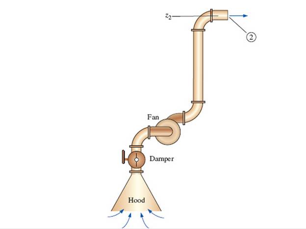
A local ventilation system (a hood and duct system) is used to remove air and contaminants produced by a welding operation (Fig. P 14-55E). The inner diameter (ID) of the duct is D = 9.06 in, its average roughness is 0.0059 in, and its total length is L = 34.0 ft. There are three elbows along the duct, each with a minor loss coefficient of 0.21. Literature from the hood manufacturer lists the hood entry loss coefficient as 4.6 based on duct velocity. When the damper is fully open, its loss coefficient is 1.8. A squirrel cage centrifugal fan with a 9.0-in inlet is available. Its performance data fit a parabolic curve of the form

The volume flow rate.
Answer to Problem 55EP
The volume flow rate is
Explanation of Solution
Given Information:
The inner diameter of the duct is
Expression for steady energy equation from point 1 in the stagnant air region to point 2 at the duct outlet
Here, the required head for the fan is
Expression for the total head loss
Here, the velocity of the air is
Expression for Reynold's number
Here, the kinematic viscosity is
Expression for relative roughness
Here, the roughness of the pipe is
Expression for the friction factor
Expression for the volume flow rate
Here, the area of the pipe is
Expression for the area of the pipe
Substitute
Expression to convert the shutoff head from inches of water column to inches of air column
Here, the density of the water is
Expression to convert
Calculation:
Refer to the Table-A-9E, "Properties of air at 1 atm pressure" to obtain the density of the air as
Substitute
Substitute
Substitute
Substitute
Substitute
Substitute
Substitute
Substitute
Substitute
Substitute
Since at the operating point the available head and the required head are equal, therefore equate equation (XII) and (XIII).
Solve Equation (XII) and Equation (XIV) to obtain the value of velocity as
Substitute
Conclusion:
The volume flow rate is
Want to see more full solutions like this?
Chapter 14 Solutions
Fluid Mechanics: Fundamentals and Applications


- Heat energy is transferred to 1.36 kg of air which causes its temperature to increase from 40" CO 468°C. Calculate, for the two separate cases of heat transfer at (a) constant volume, (b) constant pressure: the quantity of heat energy transferred, (ii) the external work done, (iii) the increase in internal energy. Take cv and cp as 0.718 and 1.005 kJ/kgK respectivelyarrow_forwardA flat circular plate is 500 mm diameter. Calculate the theoretical quantity or heat radiated per hour when its temperature is 215°C and the temperature of its surrounds is 45°C. Take the value of the radiation constant to be 5.67 × 10^11 kJ/m2s K4.arrow_forwardDescribe Atmospheric Air and how it reacts with carbon in combustionarrow_forward
- 0.5 kg of ice at —5°C is put into a vessel containing 1.8kg of water at 17°C and mixed together, the result being a mixture of ice and water at 0°C. Calculate the final masses of ice and water, taking the water equivalent of the vessel to be 0.148 kg, specific heat of ice 2.04 kilkg K and latent heat of fusion 335 kJ/kg.arrow_forwardA condenser vacuum gauge reads 715 mmHg when the barometer stands at 757 mmHg. State the absolute pressure in the condenser in kN/m2 and bars.arrow_forwardSketch and Describe a timing diagram for a 2 stroke diesel enginearrow_forward
- Manipulate the formula for converting temperature from Fahrenheit to Celsiusarrow_forwardDefine Temperature, Pressure, and Absolute Temperature.arrow_forwardAn air reservoir contains 20 kg of air at 3200 kN/m2 gauge and 16°C. Calculate the new pressure and heat energy transfer if the air is heated to 35°C. Neglect any expansion of the reservoir, take R for air = 0.287 kJ/kgK, specific heat at constant volume c, = 0.718 kJFg K, and atmospheric pressure = 100 kN/m2arrow_forward
 Principles of Heat Transfer (Activate Learning wi...Mechanical EngineeringISBN:9781305387102Author:Kreith, Frank; Manglik, Raj M.Publisher:Cengage Learning