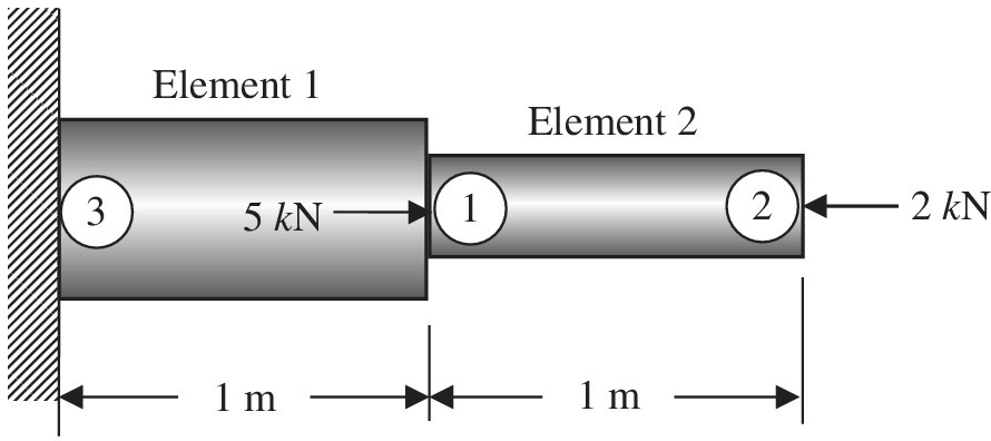
A stepped bar is clamped at one end and subjected to concentrated forces as shown.

Assume:
a. Write the element stiffness matrices of elements 1 and 2 showing the row addresses.
b. Assemble the above element stiffness matrices to obtain the following structural level equations in the form
c. Delete the rows and columns corresponding to zero DOFs to obtain the global equations in the form of
d. Determine the displacements and element forces.
Want to see the full answer?
Check out a sample textbook solution
Chapter 1 Solutions
Introduction To Finite Element Analysis And Design
Additional Engineering Textbook Solutions
Fox and McDonald's Introduction to Fluid Mechanics
Applied Statics and Strength of Materials (6th Edition)
Engineering Mechanics: Statics
Mechanics of Materials (10th Edition)
Automotive Technology: Principles, Diagnosis, and Service (5th Edition)
Fundamentals Of Thermodynamics
- II. A circular column is made of concrete [E. 4.2(10³)ksi] while being reinforced with six steel rods [Est = 29 (10³)ksi]. It is acted upon 4 in. - 30 kip by an axial force of 30 kip as shown in the figure to the right. Each rod has a diameter of 0.85 in. 3 ft Solve for the following: a) Force in each steel rod, Pst b) Force in the concrete, P. c) Stress in each steel rod, Ost = kip kip %3D ksi d) Stress in the concrete, oc = ksiarrow_forwardFor the spring system shown in the above figure, determine the displacement of each node. In the figure, the unit for the stiffness k is pound (lb) per inch. The left side of the system is fixed to a rigid wall, while the right side is displaced 0.5 inch to the right. Put a node between the rigid wall on the left and spring 1. Use the element method to establish the element stiffness matrix and then the global stiffness matrix. Apply the boundary conditions and theloads (by modifying the appropriate rows of the matrix and load vector). Solve the set of linear equations either by hand or using Matlab, Mathcad or Maple.arrow_forwardtol F = Fe F= F + F COs # F F sin a. # tan Example (L):Find the two components of the force (100 X) if: 0 = 30, 120 270° as shown in figure. F = 100 N F = 100 N 6%330 6 =120° 0 =270° 0 = 300 0 60 F = 100 N ution:arrow_forward
- Q5arrow_forwardA frame ABCD is supported by a uniformly distributed load and two concentrated loads as indicated the sketch a) Calculate the bearing reactions for the frame.b) Establish the moment diagram for the frame.c) Establish the shear force diagram for the frame.d) Establish the normal force diagram for the frame.Draw the diagrams to scalearrow_forwardHandwrite and step by step solutions The figure shows a cross section of a conventional loudspeaker. A voice coil (driven by the audio signal and connected to a lightweight cone) is suspended in a gap in an iron yoke, which has the form of a cylindrical cup with a center pedestal. The center pedestal is a permanent cylindrical magnet (length of 25mm and diameter of 20mm), which generates a magnetic field intensity of H=4x10⁴ [A/m] throughout its length. Estimate the B-field in the 2.5mm gap near the voice coil. Assume that the reluctance of the yoke is negligible. Note that the magneto-motive force of a permanent magnetic is the product of H times its length. 10 mm 2.5 mm 25 mm N voice coil Iron "yoke" permanent magnet top viewarrow_forward
- A. The frame shown in Figure I is hinged to rigid supports at A and E. Find the values of: 1. Force components of Hinge A 2. Force components of Hinge B 3. Force in Member BC 4. Force in Member BD 크 트 A 5' 3' P = 600 15 FIGURE 1 DA 3' 3' Barrow_forwardcan you please find the solution for this and thank youarrow_forwardA weightless rectangular bar BDC is loaded as shown below. There is a smooth pin at point C, a 100 N force at point D and a cable at point B. The bar and all forces are in the plane of the page (2D case). A F = 100 N 2 m 50° C 2 m 2 m 4 m a) Write the 100 N force using polar vector representation: F = |F| N@ angle 0 CCW from +x to the right. Calculate the angle theta in degrees. b) Calculate the moment of the 100 N force about point C. Give your answer in N-m (newton- meter). c) What should the direction of the 100 N force be to produce a zero moment about point B? Calculate and report the smallest angle in degrees CCW from +x to the right (angle in standard position). d) What should the direction of the 100 N force be to produce a zero moment about point A? Calculate and report the smallest angle in degrees CCW from +x to the right (angle in standard position).arrow_forward
 Principles of Heat Transfer (Activate Learning wi...Mechanical EngineeringISBN:9781305387102Author:Kreith, Frank; Manglik, Raj M.Publisher:Cengage Learning
