
Introduction To Finite Element Analysis And Design
2nd Edition
ISBN: 9781119078722
Author: Kim, Nam H., Sankar, Bhavani V., KUMAR, Ashok V., Author.
Publisher: John Wiley & Sons,
expand_more
expand_more
format_list_bulleted
Videos
Textbook Question
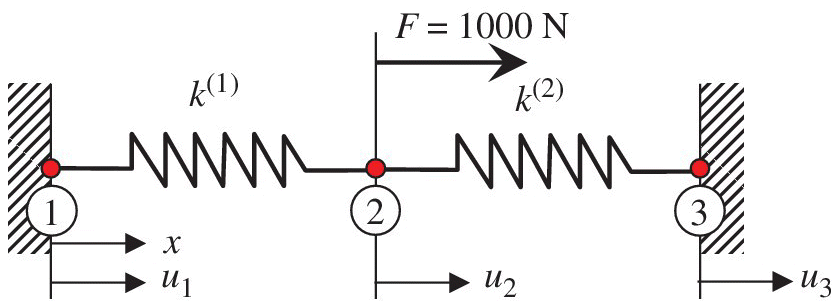
Chapter 1, Problem 2E
Calculate the displacement at node 2 and reaction forces at nodes 1 and 3 of the springs shown in the figure using two spring elements. A force
Expert Solution & Answer
Want to see the full answer?
Check out a sample textbook solution
Students have asked these similar questions
(read image, answer given)
6/86 The connecting rod AB of a certain internal-combustion engine weighs 1.2 lb with mass center at G
and has a radius of gyration about G of 1.12 in. The piston and piston pin A together weigh 1.80 lb. The
engine is running at a constant speed of 3000 rev/min, so that the angular velocity of the crank is
3000(2)/60 = 100л rad/sec. Neglect the weights of the components and the force exerted by the gas in
the cylinder compared with the dynamic forces generated and calculate the magnitude of the force on the
piston pin A for the crank angle 0 = 90°. (Suggestion: Use the alternative moment relation, Eq. 6/3, with B
as the moment center.)
Answer
A = 347 lb
3"
1.3"
B
1.7"
PROBLEM 6/86
6/85 In a study of head injury against the instrument panel of a car during sudden or crash stops where
lap belts without shoulder straps or airbags are used, the segmented human model shown in the figure is
analyzed. The hip joint O is assumed to remain fixed relative to the car, and the torso above the hip is
treated as a rigid body of mass m freely pivoted at O. The center of mass of the torso is at G with the initial
position of OG taken as vertical. The radius of gyration of the torso about O is ko. If the car is brought to a
sudden stop with a constant deceleration a, determine the speed v relative to the car with which the
model's head strikes the instrument panel. Substitute the values m = 50 kg, 7 = 450 mm, r = 800 mm, ko
= 550 mm, 0 = 45°, and a = 10g and compute v.
Answer
v = 11.73 m/s
PROBLEM 6/85
Chapter 1 Solutions
Introduction To Finite Element Analysis And Design
Ch. 1 - Answer the following descriptive questions a....Ch. 1 - Calculate the displacement at node 2 and reaction...Ch. 1 - Repeat problem 2 by changing node numbers; that...Ch. 1 - Three rigid bodies, 2,3, and 4, are connected by...Ch. 1 - Three rigid bodies, 2,3, and 4, are connected by...Ch. 1 - Consider the spring-rigid body system described in...Ch. 1 - Four rigid bodies, 1, 2, 3, and 4, are connected...Ch. 1 - Determine the nodal displacements, element forces,...Ch. 1 - In the structure shown, rigid blocks are connected...Ch. 1 - The spring-mass system shown in the figure is in...
Ch. 1 - A structure is composed of two one-dimensional bar...Ch. 1 - Two rigid masses, 1 and 2, are connected by three...Ch. 1 - Use the finite element method to determine the...Ch. 1 - Consider a tapered bar of circular cross section....Ch. 1 - The stepped bar shown in the figure is subjected...Ch. 1 - Using the direct stiffness matrix method, find the...Ch. 1 - A stepped bar is clamped at one end and subjected...Ch. 1 - A stepped bar is clamped at both ends. A force of ...Ch. 1 - Repeat problem 18 for the stepped bar shown in the...Ch. 1 - The finite element equation for the uniaxial bar...Ch. 1 - The truss structure shown in the figure supports a...Ch. 1 - The properties of the two elements of a plane...Ch. 1 - For a two-dimensional truss structure as shown in...Ch. 1 - The 2D truss shown in the figure is assembled to...Ch. 1 - For a two-dimensional truss structure as shown in...Ch. 1 - The truss shown in the figure supports force Fat...Ch. 1 - Prob. 27ECh. 1 - In the finite element model of a plane truss in...Ch. 1 - Use the finite element method to solve the plane...Ch. 1 - The plane truss shown in the figure has two...Ch. 1 - Two bars are connected as shown in the figure....Ch. 1 - The truss structure shown in the figure supports...Ch. 1 - It is desired to use the finite element method to...Ch. 1 - Determine the member force and axial stress in...Ch. 1 - Determine the normal stress in each member of the...Ch. 1 - The space truss shown has four members. Determine...Ch. 1 - The uniaxial bar shown below can be modeled as a...Ch. 1 - In the structure shown below, the temperature of...Ch. 1 - Prob. 39ECh. 1 - The three-bar truss problem in figure 1.23 is...Ch. 1 - Use the finite element method to determine the...Ch. 1 - Repeat problem 41 for the new configuration with...Ch. 1 - Repeat problem 42 with an external force added to...Ch. 1 - The properties of the members of the truss in the...Ch. 1 - Repeat problem 44 for the truss on the right side...Ch. 1 - The truss shown in the figure supports the force ....Ch. 1 - The finite element method as used to solve the...Ch. 1 - Prob. 48E
Knowledge Booster


Learn more about
Need a deep-dive on the concept behind this application? Look no further. Learn more about this topic, mechanical-engineering and related others by exploring similar questions and additional content below.Similar questions
- Using AutoCADarrow_forward340 lb 340 lb Δarrow_forward4. In a table of vector differential operators, look up the expressions for V x V in a cylindrical coordinate system. (a) Compute the vorticity for the flow in a round tube where the velocity profile is = vo [1-(³] V₂ = Vo (b) Compute the vorticity for an ideal vortex where the velocity is Ve= r where constant. 2πг (c) Compute the vorticity in the vortex flow given by Ve= r 2лг 1- exp ( r² 4vt (d) Sketch all the velocity and vorticity profiles.arrow_forward
- In the figure, Neglects the heat loss and kinetic and potential energy changes, calculate the work produced by the turbine in kJ T = ??? Steam at P=3 MPa, T = 280°C Turbine Rigid tank V = 1000 m³ Turbine Rigid tank V = 100 m³ V = 1000 m³ V = 100 m³ The valve is opened. Initially: evacuated (empty) tank O a. 802.8 Initially: Closed valve O b. 572 O c. 159.93 Od. 415 e. 627.76 equilibriumarrow_forwardPlease find the torsional yield strength, the yield strength, the spring index, and the mean diameter. Use: E = 28.6 Mpsi, G = 11.5 Mpsi, A = 140 kpsi·in, m = 0.190, and relative cost= 1.arrow_forwardA viscoelastic column is made of a material with a creep compliance of D(t)= 0.75+0.5log10t+0.18(log10t)^2 GPA^-1 for t in s. If a constant compressive stress of σ0 = –100 MPa is applied at t = 0, how long will it take (= t1/2) for the height of the column to decrease to ½ its original value? Note: You will obtain multiple answers for this problem! One makes sense physically and one does not.arrow_forward
- A group of 23 power transistors, dissipating 2 W each, are to be cooled by attaching them to a black-anodized square aluminum plate and mounting the plate on the wall of a room at 30°C. The emissivity of the transistor and the plate surfaces is 0.9. Assuming the heat transfer from the back side of the plate to be negligible and the temperature of the surrounding surfaces to be the same as the air temperature of the room, determine the length of the square plate if the average surface temperature of the plate is not to exceed 50°C. Start the iteration process with an initial guess of the size of the plate as 43 cm. The properties of air at 1 atm and the film temperature of (Ts + T)/2 = (50 + 30)/2 = 40°C are k = 0.02662 W/m·°C, ν = 1.702 × 10⁻⁵ m2 /s, Pr = 0.7255, and β = 0.003195 K–1. Multiple Choice 0.473 m 0.284 m 0.513 m 0.671 marrow_forwardA 40-cm-diameter, 127-cm-high cylindrical hot water tank is located in the bathroom of a house maintained at 20°C. The surface temperature of the tank is measured to be 44°C and its emissivity is 0.4. Taking the surrounding surface temperature to be also 20°C, determine the rate of heat loss from all surfaces of the tank by natural convection and radiation. The properties of air at 32°C are k=0.02603 W/m-K, v=1.627 x 10⁻⁵ m²/s, Pr = 0.7276, and ẞ = 0.003279 K-1 The rate of heat loss from all surfaces of the tank by natural convection is The rate of heat loss from all surfaces of the tank by radiation is W. W.arrow_forwardA 2.5-m-long thin vertical plate is subjected to uniform heat flux on one side, while the other side is exposed to cool air at 5°C. The plate surface has an emissivity of 0.73, and its midpoint temperature is 55°C. Determine the heat flux subjected on the plate surface. Uniform heat flux -Plate, € = 0.73 Cool air 5°C 7 TSUIT Given: The properties of water at Tf,c= 30°C. k=0.02588 W/m.K, v=1.608 x 10⁻⁵ m²/s Pr = 0.7282 The heat flux subjected on the plate surface is W/m²arrow_forward
- Hot water is flowing at an average velocity of 5.82 ft/s through a cast iron pipe (k=30 Btu/h-ft-°F) whose inner and outer diameters are 1.0 in and 1.2 in, respectively. The pipe passes through a 50-ft-long section of a basement whose temperature is 60°F. The emissivity of the outer surface of the pipe is 0.5, and the walls of the basement are also at about 60°F. If the inlet temperature of the water is 150°F and the heat transfer coefficient on the inner surface of the pipe is 30 Btu/h-ft².°F, determine the temperature drop of water as it passes through the basement. Evaluate air properties at a film temperature of 105°C and 1 atm pressure. The properties of air at 1 atm and the film temperature of (Ts+ T∞)/2 = (150+60)/2 = 105°F are k=0.01541 Btu/h-ft-°F. v=0.1838 × 10⁻³ ft2/s, Pr = 0.7253, and ẞ = 0.00177R-1arrow_forwardhand-written solutions only, please. correct answers upvoted!arrow_forwardhand-written solutions only, please. correct answers upvoted!arrow_forward
arrow_back_ios
SEE MORE QUESTIONS
arrow_forward_ios
Recommended textbooks for you
 Mechanics of Materials (MindTap Course List)Mechanical EngineeringISBN:9781337093347Author:Barry J. Goodno, James M. GerePublisher:Cengage Learning
Mechanics of Materials (MindTap Course List)
Mechanical Engineering
ISBN:9781337093347
Author:Barry J. Goodno, James M. Gere
Publisher:Cengage Learning
Mechanical SPRING DESIGN Strategy and Restrictions in Under 15 Minutes!; Author: Less Boring Lectures;https://www.youtube.com/watch?v=dsWQrzfQt3s;License: Standard Youtube License