
Introduction To Finite Element Analysis And Design
2nd Edition
ISBN: 9781119078722
Author: Kim, Nam H., Sankar, Bhavani V., KUMAR, Ashok V., Author.
Publisher: John Wiley & Sons,
expand_more
expand_more
format_list_bulleted
Videos
Textbook Question
Chapter 1, Problem 9E
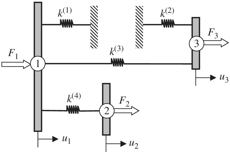
In the structure shown, rigid blocks are connected by linear springs. Imagine that only horizontal displacements are allowed. Write the global equilibrium equations
Expert Solution & Answer

Trending nowThis is a popular solution!

Students have asked these similar questions
The pickup truck weighs 3220 Ib and reaches a speed of 30 mi/hr from rest in a distance of 200 ft up the 10-percent incline with constant acceleration. Calculate the normal force under each pair of wheels and the friction force under the rear driving wheels. The effective coefficient of friction between the tires and the road is known to be at least 0.8.
1.
The figure shows a car jack to support 400kg (W=400kg). In the drawing, the angle (0) varies
between 15 and 70 °. The links are machined from AISI 1020 hot-rolled steel bars with a
minimum yield strength of 380MPa. Each link consists of two bars, one on each side of the
central bearings. The bars are 300mm in length (/) and 25 mm in width (w). The pinned ends
have the buckling constant (C) of 1.4 for out of plane buckling. The design factor (nd) is 2.5.
(1) Find the thickness (t) of the bars and the factor of safety (n).
(2) Check if the bar is an Euler beam.
D
(Read image)
Chapter 1 Solutions
Introduction To Finite Element Analysis And Design
Ch. 1 - Answer the following descriptive questions a....Ch. 1 - Calculate the displacement at node 2 and reaction...Ch. 1 - Repeat problem 2 by changing node numbers; that...Ch. 1 - Three rigid bodies, 2,3, and 4, are connected by...Ch. 1 - Three rigid bodies, 2,3, and 4, are connected by...Ch. 1 - Consider the spring-rigid body system described in...Ch. 1 - Four rigid bodies, 1, 2, 3, and 4, are connected...Ch. 1 - Determine the nodal displacements, element forces,...Ch. 1 - In the structure shown, rigid blocks are connected...Ch. 1 - The spring-mass system shown in the figure is in...
Ch. 1 - A structure is composed of two one-dimensional bar...Ch. 1 - Two rigid masses, 1 and 2, are connected by three...Ch. 1 - Use the finite element method to determine the...Ch. 1 - Consider a tapered bar of circular cross section....Ch. 1 - The stepped bar shown in the figure is subjected...Ch. 1 - Using the direct stiffness matrix method, find the...Ch. 1 - A stepped bar is clamped at one end and subjected...Ch. 1 - A stepped bar is clamped at both ends. A force of ...Ch. 1 - Repeat problem 18 for the stepped bar shown in the...Ch. 1 - The finite element equation for the uniaxial bar...Ch. 1 - The truss structure shown in the figure supports a...Ch. 1 - The properties of the two elements of a plane...Ch. 1 - For a two-dimensional truss structure as shown in...Ch. 1 - The 2D truss shown in the figure is assembled to...Ch. 1 - For a two-dimensional truss structure as shown in...Ch. 1 - The truss shown in the figure supports force Fat...Ch. 1 - Prob. 27ECh. 1 - In the finite element model of a plane truss in...Ch. 1 - Use the finite element method to solve the plane...Ch. 1 - The plane truss shown in the figure has two...Ch. 1 - Two bars are connected as shown in the figure....Ch. 1 - The truss structure shown in the figure supports...Ch. 1 - It is desired to use the finite element method to...Ch. 1 - Determine the member force and axial stress in...Ch. 1 - Determine the normal stress in each member of the...Ch. 1 - The space truss shown has four members. Determine...Ch. 1 - The uniaxial bar shown below can be modeled as a...Ch. 1 - In the structure shown below, the temperature of...Ch. 1 - Prob. 39ECh. 1 - The three-bar truss problem in figure 1.23 is...Ch. 1 - Use the finite element method to determine the...Ch. 1 - Repeat problem 41 for the new configuration with...Ch. 1 - Repeat problem 42 with an external force added to...Ch. 1 - The properties of the members of the truss in the...Ch. 1 - Repeat problem 44 for the truss on the right side...Ch. 1 - The truss shown in the figure supports the force ....Ch. 1 - The finite element method as used to solve the...Ch. 1 - Prob. 48E
Knowledge Booster


Learn more about
Need a deep-dive on the concept behind this application? Look no further. Learn more about this topic, mechanical-engineering and related others by exploring similar questions and additional content below.Similar questions
- UNIVERSIDAD NACIONAL DE SAN ANTONIO ABAD DEL CUSCO PRIMER EXAMEN PARCIAL DE MECÁNICA DE FLUIDOS I ............ Cusco, 23 de setiembre de 2024 AP. Y NOMBRES: ........ 1.- Para el tanque de la figura: a) Calcule la profundidad de la hidrolina si la profundidad del agua es de 2.8 m y el medidor del fondo del tanque da una lectura de 52.3kPa. b) Calcule la profundidad del agua si la profundidad de la hidrolina es 6.90 m y el medidor de la parte inferior del tanque registra una lectura de 125.3 kPa. Hidrolina Sp=0.90 Abertura Agua sup suge to but amulor quit y 2.- Calcule la magnitud de la fuerza resultante sobre el área A-B y la ubicación del centro de presión. Señale la fuerza resultante sobre el área y dimensione su ubicación con claridad. 3.5 ft 12 in: Oil (38-0.93) 14 in 8 inarrow_forwardplease solve this problem and give me the correct answer step by steparrow_forwardplease solve this problem step by step and show the best way that can be explainedarrow_forward
- 1 8 4 Add numbers so that the sum of any row or column equals .30 Use only these numbers: .1.2.3.4.5.6.10.11.12.12.13.14.14arrow_forwardUppgift 2 (9p) I77777 20 kN 10 kN/m 4 [m] 2 2 Bestäm tvärkrafts- och momentdiagram för balken i figuren ovan. Extrempunkter ska anges med både läge och värde i diagrammen.arrow_forward**Problem 8-45.** The man has a mass of 60 kg and the crate has a mass of 100 kg. If the coefficient of static friction between his shoes and the ground is \( \mu_s = 0.4 \) and between the crate and the ground is \( \mu_c = 0.3 \), determine if the man is able to move the crate using the rope-and-pulley system shown. **Diagram Explanation:** The diagram illustrates a scenario where a man is attempting to pull a crate using a rope-and-pulley system. The setup is as follows: - **Crate (C):** Positioned on the ground with a rope attached. - **Rope:** Connects the crate to a pulley system and extends to the man. - **Pulley on Tree:** The rope runs over a pulley mounted on a tree which redirects the rope. - **Angles:** - The rope between the crate and tree forms a \(30^\circ\) angle with the horizontal. - The rope between the tree and the man makes a \(45^\circ\) angle with the horizontal. - **Man (A):** Pulling on the rope with the intention of moving the crate. This arrangement tests the…arrow_forward
- please solve this problems follow what the question are asking to do please show me step by steparrow_forwardplease first write the line action find the forces and them solve the problem step by steparrow_forwardplease solve this problem what the problem are asking to solve please explain step by step and give me the correct answerarrow_forward
arrow_back_ios
SEE MORE QUESTIONS
arrow_forward_ios
Recommended textbooks for you
 Mechanics of Materials (MindTap Course List)Mechanical EngineeringISBN:9781337093347Author:Barry J. Goodno, James M. GerePublisher:Cengage Learning
Mechanics of Materials (MindTap Course List)
Mechanical Engineering
ISBN:9781337093347
Author:Barry J. Goodno, James M. Gere
Publisher:Cengage Learning
Mechanical SPRING DESIGN Strategy and Restrictions in Under 15 Minutes!; Author: Less Boring Lectures;https://www.youtube.com/watch?v=dsWQrzfQt3s;License: Standard Youtube License