
Videos
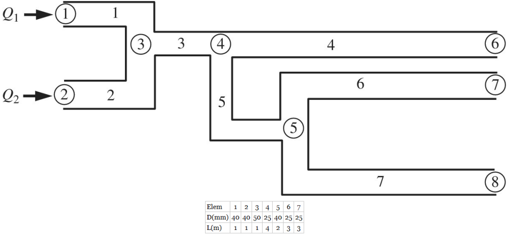
The finite element equation for the uniaxial bar can be used for other types of engineering problems if a proper analogy is applied. For example, consider the piping network shown in the figure. Each section of the network can be modeled using an FE. If the flow is laminar and steady, we can write the equations for a single pipe element as:
a. Write the element matrix equation for the flow in the pipe element.
b. The net flow rates into nodes 1 and 2 are 10 and 15 m3/s, respectively. The pressures at the nodes 6, 7, and 8 are all zero. The net flow rate into the nodes 3, 4, and 5 are all zero. What is the outflow rate for elements 4, 6, and 7?
Want to see the full answer?
Check out a sample textbook solution
Chapter 1 Solutions
Introduction To Finite Element Analysis And Design
Additional Engineering Textbook Solutions
Introduction To Programming Using Visual Basic (11th Edition)
Java How to Program, Early Objects (11th Edition) (Deitel: How to Program)
Thinking Like an Engineer: An Active Learning Approach (4th Edition)
Electric Circuits. (11th Edition)
Starting Out with Java: From Control Structures through Objects (7th Edition) (What's New in Computer Science)
Database Concepts (8th Edition)


- Q | Sign in PDE Lecture W09.pdf PDF MMB241 - Tutorial L9.pdi X PDF MMB241 - Tutorial L10.p X PDF MMB241 - Tutorial L11.p X Lecture W12-Work and X + File C:/Users/KHULEKANI/Desktop/mmb241/Lecture%20W12%20-%20Work%20and%20Energy.pdf ||! Draw | IA | a | Ask Copilot Class Work + 33 of 34 D Question 1 The engine of a 3500-N car is generating a constant power of 50 hp (horsepower) while the car is traveling up the slope with a constant speed. If the engine is operating with an efficiency of € 0.8, determine the speed of the car. Neglect drag and rolling resistance. Use g 9.81 m/s² and 1 hp = 745.7 W. 10 го Question 2 A man pushes on a 60-N crate with a force F. The force is always directed downward at an angle of 30° from the horizontal, as shown in the figure. The magnitude of the force is gradually increased until the crate begins to slide. Determine the crate's initial acceleration once it starts to move. Assume the coefficient of static friction is μ = 0.6, the coefficient of kinetic…arrow_forwardstate is Derive an expression for the volume expansivity of a substance whose equation of RT P = v-b a v(v + b)TZ where a and b are empirical constants.arrow_forwardFor a gas whose equation of state is P(v-b)=RT, the specified heat difference Cp-Cv is equal to which of the following (show all work): (a) R (b) R-b (c) R+b (d) 0 (e) R(1+v/b)arrow_forward
- of state is Derive an expression for the specific heat difference of a substance whose equation RT P = v-b a v(v + b)TZ where a and b are empirical constants.arrow_forwardTemperature may alternatively be defined as T = ди v Prove that this definition reduces the net entropy change of two constant-volume systems filled with simple compressible substances to zero as the two systems approach thermal equilibrium.arrow_forwardUsing the Maxwell relations, determine a relation for equation of state is (P-a/v²) (v−b) = RT. Os for a gas whose av Tarrow_forward
- (◉ Homework#8arrow_forwardHomework#8arrow_forwardBox A has a mass of 15 kilograms and is attached to the 20 kilogram Box B using the cord and pulley system shown. The coefficient of kinetic friction between the boxes and surface is 0.2 and the moment of inertia of the pulley is 0.5 kg * m^ 2. After 2 seconds, how far do the boxes move? A бро Barrow_forwardBox A has a mass of 15 kilograms and is attached to the 20 kilogram Box B using the cord and pulley system shown. The coefficient of kinetic friction between the boxes and surface is 0.2 and the moment of inertia of the pulley is 0.5 kg * m^2. Both boxes are 0.25 m long and 0.25 m high. The cord is attached to the bottom of Box A and the middle of box B. After 2 seconds, how far do the boxes move? A From бро Barrow_forwardarrow_back_iosSEE MORE QUESTIONSarrow_forward_iosRecommended textbooks for you
 Elements Of ElectromagneticsMechanical EngineeringISBN:9780190698614Author:Sadiku, Matthew N. O.Publisher:Oxford University Press
 Mechanics of Materials (10th Edition)Mechanical EngineeringISBN:9780134319650Author:Russell C. HibbelerPublisher:PEARSON
 Thermodynamics: An Engineering ApproachMechanical EngineeringISBN:9781259822674Author:Yunus A. Cengel Dr., Michael A. BolesPublisher:McGraw-Hill Education
 Control Systems EngineeringMechanical EngineeringISBN:9781118170519Author:Norman S. NisePublisher:WILEY
 Mechanics of Materials (MindTap Course List)Mechanical EngineeringISBN:9781337093347Author:Barry J. Goodno, James M. GerePublisher:Cengage Learning
 Engineering Mechanics: StaticsMechanical EngineeringISBN:9781118807330Author:James L. Meriam, L. G. Kraige, J. N. BoltonPublisher:WILEY
Elements Of ElectromagneticsMechanical EngineeringISBN:9780190698614Author:Sadiku, Matthew N. O.Publisher:Oxford University PressMechanics of Materials (10th Edition)Mechanical EngineeringISBN:9780134319650Author:Russell C. HibbelerPublisher:PEARSONThermodynamics: An Engineering ApproachMechanical EngineeringISBN:9781259822674Author:Yunus A. Cengel Dr., Michael A. BolesPublisher:McGraw-Hill EducationControl Systems EngineeringMechanical EngineeringISBN:9781118170519Author:Norman S. NisePublisher:WILEYMechanics of Materials (MindTap Course List)Mechanical EngineeringISBN:9781337093347Author:Barry J. Goodno, James M. GerePublisher:Cengage LearningEngineering Mechanics: StaticsMechanical EngineeringISBN:9781118807330Author:James L. Meriam, L. G. Kraige, J. N. BoltonPublisher:WILEY