
Concept explainers
Videos
The spring-mass system shown in the figure is in equilibrium under the applied loads. The element connectivity table shows node numbers associated with each element and the stiffness of each element.
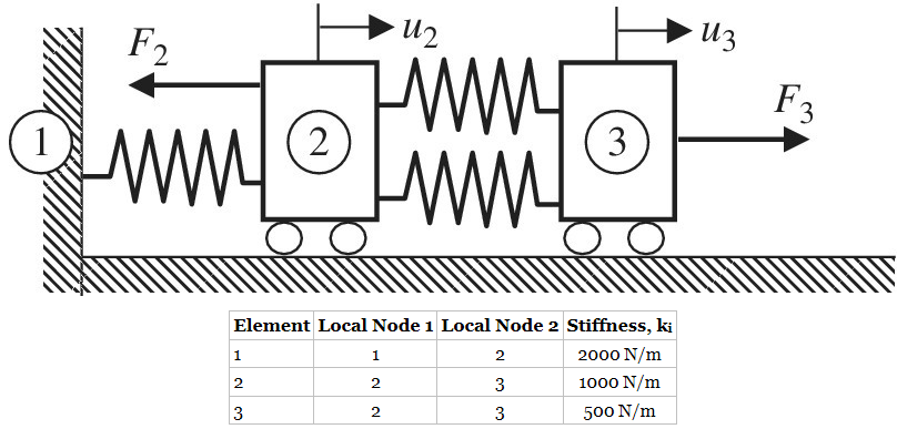
a. Write the structural matrix equations
Use
b. Apply the boundary conditions and solve for the displacement of the two masses.

Trending nowThis is a popular solution!

Chapter 1 Solutions
Introduction To Finite Element Analysis And Design


- find stress at Qarrow_forwardI had a theoretical question about attitude determination. In the attached images, I gave two axis and angles. The coefficient of the axes are the same and the angles are the same. The only difference is the vector basis. Lets say there is a rotation going from n hat to b hat. Then, you introduce a intermediate rotation s hat. So, I want to know if the DCM produced from both axis and angles will be the same or not. Does the vector basis affect the numerical value of the DCM? The DCM formula only cares about the coefficient of the axis and the angle. So, they should be the same right?arrow_forward3-15. A small fixed tube is shaped in the form of a vertical helix of radius a and helix angle y, that is, the tube always makes an angle y with the horizontal. A particle of mass m slides down the tube under the action of gravity. If there is a coefficient of friction μ between the tube and the particle, what is the steady-state speed of the particle? Let y γ 30° and assume that µ < 1/√3.arrow_forward
- The plate is moving at 0.6 mm/s when the force applied to the plate is 4mN. If the surface area of the plate in contact with the liquid is 0.5 m^2, deterimine the approximate viscosity of the liquid, assuming that the velocity distribution is linear.arrow_forward3-9. Given that the force acting on a particle has the following components: Fx = −x + y, Fy = x − y + y², F₂ = 0. Solve for the potential energy V. -arrow_forward2.5 (B). A steel rod of cross-sectional area 600 mm² and a coaxial copper tube of cross-sectional area 1000 mm² are firmly attached at their ends to form a compound bar. Determine the stress in the steel and in the copper when the temperature of the bar is raised by 80°C and an axial tensile force of 60 kN is applied. For steel, E = 200 GN/m² with x = 11 x 10-6 per °C. E = 100 GN/m² with α = 16.5 × 10⁻⁶ For copper, per °C. [E.I.E.] [94.6, 3.3 MN/m².]arrow_forward
- 3–16. A particle of mass m is embedded at a distance R from the center of a massless circular disk of radius R which can roll without slipping on the inside surface of a fixed circular cylinder of radius 3R. The disk is released with zero velocity from the position shown and rolls because of gravity, all motion taking place in the same vertical plane. Find: (a) the maximum velocity of the particle during the resulting motion; (b) the reaction force acting on the disk at the point of contact when it is at its lowest position. KAR 60° 3R M Fig. P3-16arrow_forwardI have figured out the support reactions, Ay = 240 kN, Ax = 0 kN, Ma = 639.2 kN*m and the constant term for V(x) is 240. I am not figuring out the function of x part right. Show how to derive V(x) and M(x) for this distributed load.arrow_forward2.4 (A). A 75 mm diameter compound bar is constructed by shrinking a circular brass bush onto the outside of a 50 mm diameter solid steel rod. If the compound bar is then subjected to an axial compressive load of 160 kN determine the load carried by the steel rod and the brass bush and the compressive stress set up in each material. For steel, E 210 GN/m²; for brass, E = 100 GN/m². [I. Struct. E.] [100.3, 59.7 kN; 51.1, 24.3 MN/m².]arrow_forward
- 1.7 (A). A bar ABCD consists of three sections: AB is 25 mm square and 50 mm long, BC is of 20 mm diameter and 40 mm long and CD is of 12 mm diameter and 50 mm long. Determine the stress set up in each section of the bar when it is subjected to an axial tensile load of 20 kN. What will be the total extension of the bar under this load? For the bar material, E = 210GN/m2. [32,63.7, 176.8 MN/mZ, 0.062mrn.l 10:41 مarrow_forward2.2 (A). If the maximum stress allowed in the copper of the cable of problem 2.1 is 60 MN/m2, determine the maximum tension which C3.75 kN.1 10:41 مarrow_forward1.1 (A). A 25mm squarecross-section bar of length 300mm carries an axial compressive load of 50kN. Determine the stress set up ip the bar and its change of length when the load is applied. For the bar material E = 200 GN/m2. [80 MN/m2; 0.12mm.larrow_forward
 Elements Of ElectromagneticsMechanical EngineeringISBN:9780190698614Author:Sadiku, Matthew N. O.Publisher:Oxford University Press
 Mechanics of Materials (10th Edition)Mechanical EngineeringISBN:9780134319650Author:Russell C. HibbelerPublisher:PEARSON
 Thermodynamics: An Engineering ApproachMechanical EngineeringISBN:9781259822674Author:Yunus A. Cengel Dr., Michael A. BolesPublisher:McGraw-Hill Education
 Control Systems EngineeringMechanical EngineeringISBN:9781118170519Author:Norman S. NisePublisher:WILEY
 Mechanics of Materials (MindTap Course List)Mechanical EngineeringISBN:9781337093347Author:Barry J. Goodno, James M. GerePublisher:Cengage Learning
 Engineering Mechanics: StaticsMechanical EngineeringISBN:9781118807330Author:James L. Meriam, L. G. Kraige, J. N. BoltonPublisher:WILEY