
Concept explainers
Videos
Scanning Confocal Microscopy
Although modern microscopes are marvels of optical engineering, their basic design is not too different from the 1665 compound microscope of Robert Hooke. Recently, advances in optics, lasers, and computer technology have made practical a new kind of optical microscope, the scanning confocal microscope. This microscope is capable of taking images of breathtaking clarity.
The figure shows the microscope’s basic principle of operation. The left part of the figure shows how the translucent specimen is illuminated by light from a laser. The laser beam is converted to a diverging bundle of rays by suitable optics, reflected off a mirror, then directed through a microscope objective lens to a focus within the sample. The microscope objective focuses the laser beam to a very small (≈ 0.5 μm) spot. Note that light from the laser passes through other regions of the specimen but, because the rays are not focused in those regions, they are not as intensely illuminated as is the point at the focus. This is the first important aspect of the design: Very intensely illuminate one very small volume of the sample while leaving other regions only weakly illuminated.
As shown in the right half of the figure, light is reflected from all illuminated points in the sample and passes back through the objective lens. The mirror that had reflected the laser light downward is actually a partially transparent
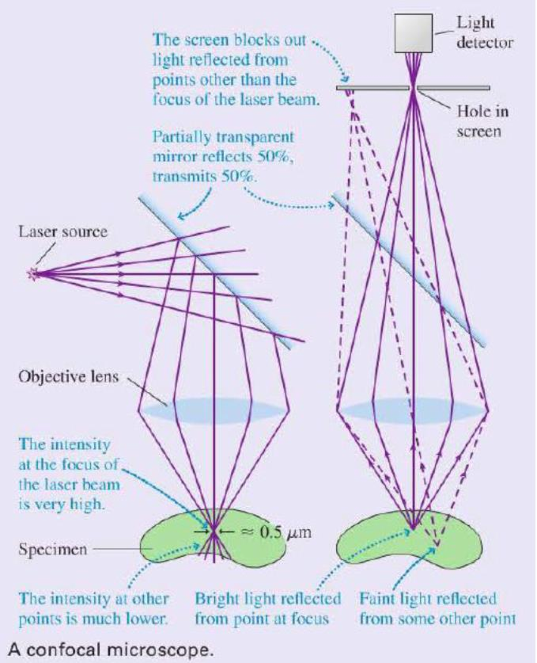
mirror that reflects 50% of the light and transmits 50%. Thus half of the light reflected upward from the sample passes through the mirror and is focused on a screen containing a small hole. Because of the hole, only light rays that emanate from the brightly illuminated volume in the sample can completely pass through the hole and reach the light detector behind it. Rays from other points in the sample either miss the hole completely or are out of locus when they reach the screen, so that only a small fraction of them pass through the hole. This second key design aspect limits the detected light to only those rays that are emitted from the point in the sample at which the laser light was originally focused.
So we see that (a) the point in the sample that is at the focus of the objective is much more intensely illuminated than any other point, so it reflects more rays than any other point, and (b) the hole serves to further limit the detected rays to only those that emanate from the focus. Taken together, these design aspects ensure the detected light comes from a very small, very well-defined volume in the sample.
The microscope as shown would only be useful for examining one small point in the sample. To make an actual image, the objective is scanned across the sample while the intensity is recorded by a computer. This procedure builds up an image of the sample one scan line at a time. The final result is a picture of the sample in the very narrow plane in which the laser beam is focused. Different planes within the sample can be imaged by moving the objective up or down before scanning. It is actually possible to make three dimensional images of a specimen in this way.
The improvement in contrast and resolution over conventional microscopy can be striking. The images show a section of a mouse kidney taken using conventional and confocal microscopy. Because light reflected from all parts of the specimen reaches the camera in a conventional microscope, that image appears blurred and has low contrast. The confocal microscope image represents a single plane or slice of the sample, and many details become apparent that are invisible in the conventional image.

A section of fluorescently stained mouse kidney imaged using standard optical microscopy (left) and scanning confocal microscopy (right).
The following questions are related to the passage “Scanning Con focal Microscopy” on the previous page.
1. A laser beam consists of parallel rays of light. To convert this light to the diverging rays required for a scanning confocal microscope requires
- A. A converging lens.
- B. A diverging lens.
- C. Either a converging or a diverging lens.
Want to see the full answer?
Check out a sample textbook solution
Chapter P Solutions
College Physics: A Strategic Approach (3rd Edition)
Additional Science Textbook Solutions
Cosmic Perspective Fundamentals
Microbiology: An Introduction
Campbell Biology in Focus (2nd Edition)
Organic Chemistry (8th Edition)
Human Anatomy & Physiology (2nd Edition)
Human Physiology: An Integrated Approach (8th Edition)


- No chatgpt plsarrow_forwardThe law of reflection applies to Question 14Select one: a. specular reflection b. irregular reflection c. All of these d. diffuse reflectionarrow_forwardAccording to your book "normal" human body temperature is considered to be ________? Select one: a. none of these b. 98.6°C c. 37°C d. 100°Carrow_forward
- Problem Seven. A football receiver running straight downfield at 5.60 m/s is 11.5 m in front of the quarterback when a pass is thrown downfield at an angle of 35.0° above the horizon. 8.) If the receiver never changes speed and the ball is caught at the same height from which it was thrown, find the distance between the quarterback and the receiver when the catch is made. (A) 21.3 (B) 17.8 (C) 18.8 (D) 19.9 (E) 67.5arrow_forwardWhen two bar magnets are near each other, the north pole of one of the magnets experiences what type of force from the other magnet? 1. both an attractive force and a repulsive force 2. a Coulomb force 3. only an attractive force 4. only a repulsive forcearrow_forwardWhat can be said about the electric force between two charged particles? It varies as 1/r. It depends only on the magnitudes of the charges. It is much, much greater than the attractive gravitational force. It is repulsive for unlike charges.arrow_forward
- A piece of copper originally 305mm long is pulled in tension with a stress of 276MPa. If the deformation is elastic, what will be the resultant elongation. E for copper is 110Gpaarrow_forwardPlease solve and answer the problem correctly please. Be sure to give explanations on each step and write neatly please. Thank you!!arrow_forwardIn the figures, the masses are hung from an elevator ceiling. Assume the velocity of the elevator is constant. Find the tensions in the ropes (in N) for each case. Note that 0₁ = 35.0°, 0₂ = 55.0°, 03 = 60.0°, m₁ = 3.00 kg, and m2 = 7.00 kg. (Due to the nature of this problem, do not use rounded intermediate values-including answers submitted in WebAssign-in your calculations.) (a) Τι WY NY MY T3 e₁ T₁ = N = N = N (b) 18 Τι = Τι T3 = || || || = T T Ts m₂ N N N 02 T₂ T3 m₁arrow_forward
- You are working with a movie director and investigating a scene with a cowboy sliding off a tree limb and falling onto the saddle of a moving horse. The distance of the fall is several meters, and the calculation shows a high probability of injury to the cowboy from the stunt. Let's look at a simpler situation. Suppose the director asks you to have the cowboy step off a platform 2.55 m off the ground and land on his feet on the ground. The cowboy keeps his legs straight as he falls, but then bends at the knees as soon as he touches the ground. This allows the center of mass of his body to move through a distance of 0.660 m before his body comes to rest. (Center of mass will be formally defined in Linear Momentum and Collisions.) You assume this motion to be under constant acceleration of the center of mass of his body. To assess the degree of danger to the cowboy in this stunt, you wish to calculate the average force upward on his body from the ground, as a multiple of the cowboy's…arrow_forwardA box of mass m = 2.00 kg is released from rest at the top of an inclined plane as seen in the figure. The box starts out at height h =0.200 m above the top of the table, the table height is H = 2.00 m, and 0 = 41.0°. H m (a) What is the acceleration (in m/s²) of the box while it slides down the incline? m/s² (b) What is the speed (in m/s) of the box when it leaves the incline? m/s (c) At what horizontal distance (in m) from the end of the table will the box hit the ground? m (d) How long (in s) from when the box is released does it hit the ground? S (e) Does the box's mass affect any of your above answers? Yes Noarrow_forward(a) A sphere made of rubber has a density of 0.940 g/cm³ and a radius of 7.00 cm. It falls through air of density 1.20 kg/m³ and has a drag coefficient of 0.500. What is its terminal speed (in m/s)? m/s (b) From what height (in m) would the sphere have to be dropped to reach this speed if it fell without air resistance? marrow_forward
 University Physics Volume 3PhysicsISBN:9781938168185Author:William Moebs, Jeff SannyPublisher:OpenStax
 Physics for Scientists and Engineers: Foundations...PhysicsISBN:9781133939146Author:Katz, Debora M.Publisher:Cengage Learning
 Principles of Physics: A Calculus-Based TextPhysicsISBN:9781133104261Author:Raymond A. Serway, John W. JewettPublisher:Cengage Learning
 Glencoe Physics: Principles and Problems, Student...PhysicsISBN:9780078807213Author:Paul W. ZitzewitzPublisher:Glencoe/McGraw-Hill
 Physics for Scientists and Engineers with Modern ...PhysicsISBN:9781337553292Author:Raymond A. Serway, John W. JewettPublisher:Cengage Learning