
Videos
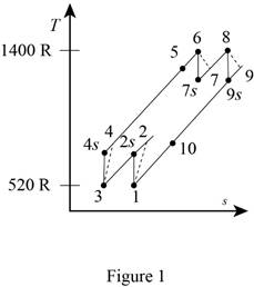
A gas turbine operates with a regenerator and two stages of reheating and intercooling. Air enters this engine at 14 psia and 60°F, the pressure ratio for each stage of compression is 3, the air temperature when entering a turbine is 940°F, the engine produces 1000 hp, and the regenerator operates perfectly. The isentropic efficiency of each compressor is 88 percent and that of each turbine is 93 percent. Which process of the cycle loses the greatest amount of work potential? The temperature of the heat source is the same as the maximum cycle temperature, and the temperature of the heat sink is the same as the minimum cycle temperature. Use constant specific heats at room temperature.
Which process of the cycle loses the greatest amount of work potential.
Answer to Problem 151P
The exergy destruction associated with process 1-2 and 3-4 is
The exergy destruction associated with process 5-6 and 7-8 is
The exergy destruction associated with process 6-7 and 8-9 is
The exergy destruction associated with process 10-1 and 2-3 is
The exergy destruction associated at regenerator is
During the heat rejection process the highest energy destruction occurs.
Explanation of Solution
Draw the
Write the expression for the temperature and pressure relation for the isentropic process 1-2s.
Here, the pressure ratio is
Write the expression for the efficiency of the compressor
Here, the specific heat at constant pressure is
Write the expression for the temperature and pressure relation ratio for the expansion process 6-7s.
Here, temperature at state 7s for isentropic process is
Write the expression for the efficiency of the turbine
Here, temperature at state 7 is
Write the expression to calculate the heat input for the two-stage gas turbine
Here, the specific heat of air at constant pressure is
Write the expression to calculate the heat output for the two-stage gas turbine
Write the expression for the exergy destruction during the process of as steam from an inlet to exit state.
Here, entropy generation is
Write the expression of exergy destruction for process 1-2
Here, pressure at state 2 is
Write the expression of exergy destruction for process 5-6
Here, pressure at state 5 is
Write the expression of exergy destruction for process 6-7
Here, pressure at state 7 is
Write the expression of exergy destruction for process 10-1
Here, pressure at state 10 is
Write the expression of exergy destruction for regenerator
Conclusion:
Substitute
Substitute
Substitute
Substitute
The regenerator is ideal, the effectiveness is 100% and therefore,
Substitute
Substitute
Substitute
Thus, the exergy destruction associated with process 1-2 and 3-4 is
Substitute
Thus, the exergy destruction associated with process 5-6 and 7-8 is
Substitute
Thus, the exergy destruction associated with process 6-7 and 8-9 is
Substitute
Thus, the exergy destruction associated with process 10-1 and 2-3 is
Substitute
Thus, the exergy destruction associated at regenerator is
During the heat rejection process the highest energy destruction occurs.
Want to see more full solutions like this?
Chapter 9 Solutions
THERMODYNAMICS (LL)-W/ACCESS >CUSTOM<


- The design of the gear-and-shaft system shown requires that steel shafts of the same diameter be used for both AB and CD. It is further required that the angle D through which end D of shaft CD rotates not exceed 1.5°. Knowing that G = 77.2 GPa, determine the required diameter of the shafts. 40 mm 400 mm 100 mm 600 mm T-1000 N-m Darrow_forwardAssume a Space Launch System (Figure 1(a)) that is approximated as a cantilever undamped single degree of freedom (SDOF) system with a mass at its free end (Figure 1(b)). The cantilever is assumed to be massless. Assume a wind load that is approximated with a concentrated harmonic forcing function p(t) = posin(ωt) acting on the mass. The known properties of the SDOF and the applied forcing function are given below. • Mass of SDOF: m =120 kip/g • Acceleration of gravity: g = 386 in/sec2 • Bending sectional stiffness of SDOF: EI = 1015 lbf×in2 • Height of SDOF: h = 2000 inches • Amplitude of forcing function: po = 6 kip • Forcing frequency: f = 8 Hzarrow_forward13.44 The end of a cylindrical liquid cryogenic propellant tank in free space is to be protected from external (solar) radiation by placing a thin metallic shield in front of the tank. Assume the view factor Fts between the tank and the shield is unity; all surfaces are diffuse and gray, and the surroundings are at 0 K. Tank T₁ Shield, T T₁ = 100 K E1 Solar irradiation Gs ε₁ = ε₂ = 0.05 ε₁ = 0.10 Gs = 1250 W/m² E2 Find the temperature of the shield T, and the heat flux (W/m²) to the end of the tank.arrow_forward
- question 664 thank youarrow_forward13.38 Consider the attic of a home located in a hot climate. The floor of the attic is characterized by a width of L₁ = 8 m while the roof makes an angle of 0 = 30° from the horizontal direction, as shown in the schematic. The homeowner wishes to reduce the heat load to the home by adhering bright aluminum foil (ε = 0.07) onto the surfaces of the attic space. Prior to installation of the foil, the surfaces are of emissivity & = 0.90. Attic A2, 82, T2 0 = 30° A1, E1, T₁ 土 L₁ = 8 m (a) Consider installation on the bottom of the attic roof only. Determine the ratio of the radiation heat transfer after to before the installation of the foil. (b) Determine the ratio of the radiation heat transfer after to before installation if the foil is installed only on the top of the attic floor. (c) Determine the ratio of the radiation heat transfer if the foil is installed on both the roof bottom and the floor top.arrow_forward13.1 Determine F2 and F2 for the following configura- tions using the reciprocity theorem and other basic shape factor relations. Do not use tables or charts. (a) Small sphere of area A, under a concentric hemi- sphere of area A₂ = 3A₁ A₂ A1 (a) (b) Long duct. Also, what is F₁₂? A₂ Αν (b) (c) Long inclined plates (point B is directly above the center of A₁) B 100 mm A₂ - 220 mm (c) (d) Long cylinder lying on infinite plane + A₁ Az (d) (e) Hemisphere-disk arrangement -A₂, hemisphere, diameter D A₂ A₁, disk, diameter D/2 (e) (f) Long, open channel 1 m AA₂ 2 m (f) (g) Long cylinders with A₁ = 4A₁. Also, what is F₁₂? -D₁ A1 -A₂ -D2 (e) (h) Long, square rod in a long cylinder. Also, what is F22? w=D/5 18 A₁ -A2 (h) -Darrow_forward
- 13.9 Determine the shape factor, F12, for the rectangles shown. 6 m 1 3 m 6 m 1 m 2 6 m 1 0.5 m 2 1 m (a) Perpendicular rectangles without a common edge. -1 m. (b) Parallel rectangles of unequal areas.arrow_forwardI keep getting the wrong answer i have gotten 6519.87 and 319.71arrow_forwardthank you for previous answer I apologize if the acceleration was unclear it is underlined now along with values in tablesarrow_forward
- ११११११११ TABLE Much 160,000kg Croll 0,005 CD Ap Par ng При nchs 0.15 5m² 1.2kg/m³ 0.98 0.9 0,98 0,9 0,88 IF 20 10 to add The train is going to make several stops along its journey. It will be important for the train to accelerate quickdy to get back up to speed. In order to get Tesla Model S motors until we get the combined The Forque and power needed we are goins bined power and forque needed to accelerate from 0 to 324 km/hr in less than 5 Minutes. Tesla Prated 270 kW Tesla Trated Twheel ng Jaxle 440 NM 20 8.5kgm² 0.45M a) What is the minimum whole number of Tesla Motors required to achieve accelerate the train from 0 to 324 km/hr in less than 5 Nnutes? Seperate the acceleration into constant torque and constant power 0. b) How long does it take the train to accelerate from 0 to 324 km/hr with the number of Tesla motors from part a? c) Using Matlab plot the relocity profile as a function of time, Is this a constant acceleration profile? Barrow_forwardExample find f(t)? -4s F(s)= (s² + 4)²arrow_forwarddraw a kinematic diagramarrow_forward
 Elements Of ElectromagneticsMechanical EngineeringISBN:9780190698614Author:Sadiku, Matthew N. O.Publisher:Oxford University Press
 Mechanics of Materials (10th Edition)Mechanical EngineeringISBN:9780134319650Author:Russell C. HibbelerPublisher:PEARSON
 Thermodynamics: An Engineering ApproachMechanical EngineeringISBN:9781259822674Author:Yunus A. Cengel Dr., Michael A. BolesPublisher:McGraw-Hill Education
 Control Systems EngineeringMechanical EngineeringISBN:9781118170519Author:Norman S. NisePublisher:WILEY
 Mechanics of Materials (MindTap Course List)Mechanical EngineeringISBN:9781337093347Author:Barry J. Goodno, James M. GerePublisher:Cengage Learning
 Engineering Mechanics: StaticsMechanical EngineeringISBN:9781118807330Author:James L. Meriam, L. G. Kraige, J. N. BoltonPublisher:WILEY