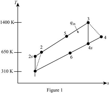
The exergy destruction associated with each process of the Brayton cycle and the exergy of the exhaust gases at the exit of the regenerator.
Answer to Problem 150P
The exergy destruction associated with process 1-2 for Brayton cycle is
The exergy destruction associated with process 3-4 for Brayton cycle is
The exergy destruction associated with regeneration process for Brayton cycle is
The exergy destruction associated with process 5-3 for Brayton cycle is
The exergy destruction associated with process 6-1 for Brayton cycle is
The exergy of the exhaust gases at the exit of the regenerator is
Explanation of Solution
Draw

Write the expression of pressure ratio for the regenerative Brayton cycle
Here, pressure at state 2 is
Write the pressure ratio and pressure relation for the process 3-4.
Here, pressure at state 3 is
Write the expression of efficiency of the turbine
Here, enthalpy at state 3 is
Write the expression of heat added due to regeneration
Here, the effectiveness of the regenerator is
Write the expression of net work output of the regenerative Brayton cycle
Here, the work output by the turbine is
Write the expression of heat input to the regenerative Brayton cycle
Write the expression of heat rejected by the regenerative Brayton cycle
Write the expression of specific enthalpy at state 6
Write the specific enthalpy relation for the regenerator.
Write the expression of exergy destruction associated with the process 1-2 for Brayton cycle
Here, the gas constant of air is R, entropy of air at state 2 as a function of temperature only is
Write the expression of exergy destruction for process 3-4
Here, entropy of air at state 3 as a function of temperature is
Write the expression of exergy destruction for Brayton cycle
Here, entropy of air at state 5 as a function of temperature alone is
Write the expression of exergy destruction for process 5-3
Here, the temperature of the heat source is
Write the expression of exergy destruction for process 6-1
Here, the temperature of the sink is
Write the expression of stream exergy at the exit of the regenerator (state 6)
Here, the specific enthalpy of the surroundings is
Write the expression of change entropy for the exit of the regenerator
Here, entropy of air at the surroundings as a function of temperature alone is
Conclusion:
Refer Table A-17, “Ideal gas properties of air”, obtain the properties of air at 310 K
Substitute 900 kPa for
Substitute
Refer Table A-17, “Ideal gas properties of air”, obtain the properties of air at 50.06
Substitute
Substitute 0.80 for
Substitute
Substitute
Substitute
Substitute 310.24
Substitute 659.84
Refer Table A-17, “Ideal gas properties of air”, obtain the properties of air at 310 K
Substitute 300 K for
Thus, the exergy destruction associated with process 1-2 for Brayton cycle is
Substitute 300 K for
Thus, the exergy destruction associated with process 3-4 for Brayton cycle is
Substitute 300 K for
Thus, the exergy destruction associated with regeneration process for Brayton cycle is
Substitute 300 K for
Thus, the exergy destruction associated with process 5-3 for Brayton cycle is
Substitute 300 K for
Thus, the exergy destruction associated with process 6-1 for Brayton cycle is
Refer Table A-17, “Ideal gas properties of air”, obtain the properties of air at 300 K
Substitute
Substitute
Thus, the exergy of the exhaust gases at the exit of the regenerator is
Want to see more full solutions like this?
Chapter 9 Solutions
THERMODYNAMICS (LL)-W/ACCESS >CUSTOM<
- What is the moment of Inertia of this body? What is Ixx, Iyy, and Izzarrow_forwardi need the The shaft is supported by a smooth thrust bearing at AA and a smooth journal bearing at BB. Draw the shear diagram for the shaft. Follow the sign convention.arrow_forward4- In the system shown in the figure, the water velocity in the 12 in. diameter pipe is 8 ft/s. Determine the gage reading at position 1. Elevation 170 ft 1 Elevation 200 ft | 8 ft, 6-in.-diameter, 150 ft, 12-in.-diameter, f = 0.020 f = 0.020 A B Hints: the minor losses should consider the contraction loss at A and the expansion loss at B.arrow_forward
- What is the moment of Inertia of this body? What is Ixx, Iyy, and Izzarrow_forwardConsider a glass window (Hight = 1.2 m, Width = 2 m). The room thatfaces the window are maintained at 25 o C. The average temperature ofthe inner surface of the window is 5 o C. Calculate the total heat transferrate from through the window a) IdenCfy what type(s) of convecCon is important (circle one). • external forced (Chapter 7)• internal forced (Chapter 8)• natural convecCon (Chapter 9)• boiling and condensaCon (Chapter 10)b) IdenCfy the necessary equaCon(s) needed to solve the problem. c) IdenCfy important fluid properCes you need to solve the problem. d) Calculate the total heat transferred.arrow_forwardWater is condensing on a square plate (0.5 m x 0.5 m) placed verCcally. If the desired rate ofcondensaCon is 0.016 kJ/s, determine the necessary surface temperature of the plate at atmosphericpressure. Assume the film temperature of 90 o C for evaluaCon of fluid properCes of water and thesurface temperature of 80 o C for the evaluaCon of modified latent heat of vaporizaConarrow_forward
- Water at 20 o C enters the 4 cm-diameter, 14 m-long tube at a rate of 0.8 kg/s. The surfacetemperature of the pipe is maintained at 165 o Cby condensing geothermal stream at the shellside of the heat exchanger. Use water properCesat 85 o C for all calculaCons.(a) Show that the water flow is turbulent and thermally fully developed. (b) EsCmate the heat transfer coefficient for convecCve heat transfer from the pipe to the water. For a fully developed turbulent flow within the smooth pipe, the Nu number can becalculated from the following equaCon:(c) Calculate the exit temperature of the water. (d) Share your opinion on whether the use of water properties at 85°C is appropriate. Yes or No because:arrow_forwardConsider a hot automotive engine, which can beapproximated as a 0.5-m-high, 0.40-m-wide, and 0.8-m-long rectangular block. The bottom surface of the block isat a temperature of 100°C and has an emissivity of 0.95.The ambient air is at 20°C, and the road surface is at25°C. Determine the rate of heat transfer from the bottomsurface of the engine block by convection and radiationas the car travels at a velocity of 80 km/h. Assume theflow to be turbulent over the entire surface because of theconstant agitation of the engine block. a) Calculate convective heat transfer coefficient (h). b) Calculate the total heat transfer ratearrow_forward8 mm- Top view -200 mm-180 mm- D B B 12 mm Side view B -8 mm D PROBLEM 1.56 In an alternative design for the structure of Prob. 1.55, a pin of 10-mm-diameter is to be used at A. Assuming that all other specifications remain unchanged, determine the allowable load P if an overall factor of safety of 3.0 is desired. PROBLEM 1.55 In the structure shown, an 8- mm-diameter pin is used at A, and 12-mm- diameter pins are used at B and D. Knowing that the ultimate shearing stress is 100 MPa at all connections and that the ultimate normal stress is 250 MPa in each of the two links joining B and D, determine the allowable load P if an overall factor of safety of 3.0 is desired. 20 mm P 8 mm- 12 mm- Front viewarrow_forward
- Where on the beam below is the Maximum Deflection likely to occur? 2P A "ती Point A Point B Point C Point D Point B or Point D ८ B पarrow_forwardSign in ||! PDE 321 proje X IMB321 PDF Lecture 5 X PDF Planet Ec X PDF Planet Ec X PDF PEABWX PDF meeting x PDF GSS Quo X PDF File C:/Users/KHULEKANI/Downloads/CIVE%20281%20Ass-2.pdf Draw | | All | a | Ask Copilot + 1 of 7 | D SOLUTION B PROBLEM 12.16 Block 4 has a mass of 40 kg, and block B has a mass of 8 kg. The coefficients of friction between all surfaces of contact are μ, = 0.20 H = 0.15. Knowing that P = 50 N→, determine (a) the acceleration of block B, (b) the tension in the cord. Constraint of cable: 2x + (x-x1) = x + x = constant. a+ag = 0, or aB = -a Assume that block A moves down and block B moves up. Block B: +/ΣF, = 0: NAB - WB cos 0 = 0 =ma: -T+μN + Wsin = We as g + ΣΕ We Eliminate NAB and aB- NAB B Nas HN UNA A NA -T+W(sin+μcоsе) = WB- g VD"M- g Block A: +/ΣF, = 0: NA-NAB - W₁cos + Psinė = 0 N₁ = N AB+W cose - Psin = (WB+WA)cose - Psinė ΣF=ma -T+Wsino-FAB-F + Pcos = CIVE 281 X + Ждал g Q | го || حالم ☑arrow_forwardWhere on the below beam is the Maxiumum Slope likely to occur? 120 Point A Point B Point C Point B or Point C B сarrow_forward
 Elements Of ElectromagneticsMechanical EngineeringISBN:9780190698614Author:Sadiku, Matthew N. O.Publisher:Oxford University Press
 Mechanics of Materials (10th Edition)Mechanical EngineeringISBN:9780134319650Author:Russell C. HibbelerPublisher:PEARSON
 Thermodynamics: An Engineering ApproachMechanical EngineeringISBN:9781259822674Author:Yunus A. Cengel Dr., Michael A. BolesPublisher:McGraw-Hill Education
 Control Systems EngineeringMechanical EngineeringISBN:9781118170519Author:Norman S. NisePublisher:WILEY
 Mechanics of Materials (MindTap Course List)Mechanical EngineeringISBN:9781337093347Author:Barry J. Goodno, James M. GerePublisher:Cengage Learning
 Engineering Mechanics: StaticsMechanical EngineeringISBN:9781118807330Author:James L. Meriam, L. G. Kraige, J. N. BoltonPublisher:WILEY


