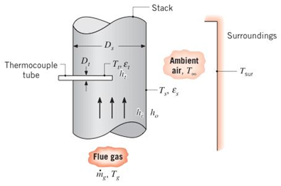
The temperature of flue gases flowing through the large stack of a boiler is measured by means of a thermocouple enclosed within a cylindrical tube as shown. The tube axis is oriented normal to the gas flow, and the thermo couple senses a temperature T, corresponding to that of the tube surface. The gas flow rate and temperature are designated as the m g and T g . respectively, and the gas flow may be assumed to be fully developed. The stack is fabricated from sheet metal that is at a uniform temperature T ∞ and is exposed to ambient air at T s , and large surroundings at T s u r . The convection coefficient associated with the outer surface of the duct is designated as h 0 , while those associated with the inner surface of the duct and the tube surface are designated as h i and h t , respectively. The tube and duct surface emissivities are designated as ε t and ε s respectively. (a) Neglecting conduction losses along the thermocouple tube, develop an analysis that could be used topredict the error ( T g − T t ) in the temperature measurement. (b) Assuming the flue gas (o have the properties ofatmospheric air, evaluate the error for T t = 300 ° C , D s = = 0.6 m , D t = 10 mm,mg = 1 kg/s , T ∞ = T s u r = 27 ° C , ε t = ε s = 0.8 , and h 0 = 25 W/m 2 ⋅ K .
The temperature of flue gases flowing through the large stack of a boiler is measured by means of a thermocouple enclosed within a cylindrical tube as shown. The tube axis is oriented normal to the gas flow, and the thermo couple senses a temperature T, corresponding to that of the tube surface. The gas flow rate and temperature are designated as the m g and T g . respectively, and the gas flow may be assumed to be fully developed. The stack is fabricated from sheet metal that is at a uniform temperature T ∞ and is exposed to ambient air at T s , and large surroundings at T s u r . The convection coefficient associated with the outer surface of the duct is designated as h 0 , while those associated with the inner surface of the duct and the tube surface are designated as h i and h t , respectively. The tube and duct surface emissivities are designated as ε t and ε s respectively. (a) Neglecting conduction losses along the thermocouple tube, develop an analysis that could be used topredict the error ( T g − T t ) in the temperature measurement. (b) Assuming the flue gas (o have the properties ofatmospheric air, evaluate the error for T t = 300 ° C , D s = = 0.6 m , D t = 10 mm,mg = 1 kg/s , T ∞ = T s u r = 27 ° C , ε t = ε s = 0.8 , and h 0 = 25 W/m 2 ⋅ K .
Solution Summary: The author explains the error in temperature measurement and the expression for heat convection.
The temperature of flue gases flowing through the large stack of a boiler is measured by means of a thermocouple enclosed within a cylindrical tube as shown. The tube axis is oriented normal to the gas flow, and the thermo couple senses a temperature T, corresponding to that of the tube surface. The gas flow rate and temperature are designated as the
m
g
and
T
g
. respectively, and the gas flow may be assumed to be fully developed. The stack is fabricated from sheet metal that is at a uniform temperature
T
∞
and is exposed to ambient air at
T
s
, and large surroundings at
T
s
u
r
. The convection coefficient associated with the outer surface of the duct is designated as
h
0
, while those associated with the inner surface of the duct and the tube surface are designated as
h
i
and
h
t
, respectively. The tube and duct surface emissivities are designated as
ε
t
and
ε
s
respectively.
(a) Neglecting conduction losses along the thermocouple tube, develop an analysis that could be used topredict the error
(
T
g
−
T
t
)
in the temperature measurement.
(b) Assuming the flue gas (o have the properties ofatmospheric air, evaluate the error for
T
t
=
300
°
C
,
D
s
=
=
0.6
m
,
D
t
=
10
mm,mg
=
1
kg/s
,
T
∞
=
T
s
u
r
=
27
°
C
,
ε
t
=
ε
s
=
0.8
,
and
h
0
=
25
W/m
2
⋅
K
.
The 2-mass system shown below depicts a disk which rotates about its center and has rotational
moment of inertia Jo and radius r. The angular displacement of the disk is given by 0. The spring
with constant k₂ is attached to the disk at a distance from the center. The mass m has linear
displacement & and is subject to an external force u. When the system is at equilibrium, the spring
forces due to k₁ and k₂ are zero. Neglect gravity and aerodynamic drag in this problem. You may
assume the small angle approximation which implies (i) that the springs and dampers remain in
their horizontal / vertical configurations and (ii) that the linear displacement d of a point on the
edge of the disk can be approximated by d≈re.
Ө
K2
www
m
4
Cz
777777
Jo
Make the following assumptions when analyzing the forces and torques:
тв
2
0>0, 0>0, x> > 0, >0
Derive the differential equations of motion for this dynamic system. Start by sketching
LARGE and carefully drawn free-body-diagrams for the disk and the…
A linear system is one that satisfies the principle of superposition. In other words, if an input u₁
yields the output y₁, and an input u2 yields the output y2, the system is said to be linear if a com-
bination of the inputs u = u₁ + u2 yield the sum of the outputs y = y1 + y2.
Using this fact, determine the output y(t) of the following linear system:
given the input:
P(s) =
=
Y(s)
U(s)
=
s+1
s+10
u(t) = e−2+ sin(t)
=e
The manometer fluid in the figure given below is mercury where D = 3 in and h = 1 in. Estimate the volume flow in the tube (ft3/s) if the flowing fluid is gasoline at 20°C and 1 atm. The density of mercury and gasoline are 26.34 slug/ft3 and 1.32 slug/ft3 respectively. The gravitational force is 32.2 ft/s2.
Need a deep-dive on the concept behind this application? Look no further. Learn more about this topic, mechanical-engineering and related others by exploring similar questions and additional content below.


 Principles of Heat Transfer (Activate Learning wi...Mechanical EngineeringISBN:9781305387102Author:Kreith, Frank; Manglik, Raj M.Publisher:Cengage Learning