Concept explainers
Videos
A bayonet cooler is used to reduce the temperature of a pharmaceutical fluid. The pharmaceutical fluid flows through the cooler, which is fabricated of
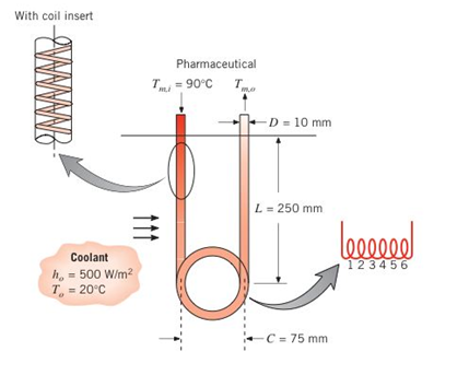
(a) Determine the outlet temperature of the pharmaceutical fluid.
(b) It is desired to further reduce the outlet temperature of the pharmaceutical. However, because the cooling process is just one pan of an intricate processing operation, flow rates cannot be changed. A young engineer suggests that the outlet temperature might be reduced by inserting stainless steel coiled springs into the straight sections of the cooler with the notion that the springs will disturb the how adjacent to the inner tube wall and, in turn, increase the heat transfer coefficient at the inner tube wall. A senior engineer asserts that insertion of the springs should double the heat transfer coefficient at the straight inner tube walls. Determine the outlet temperature of the pharmaceutical fluid with the springs inserted into the tubes, assuming the senior engineer is correct in his assertion.
(c) Would you expect the outlet temperature of the pharmaceutical to depend on whether the springs have a left-hand or right-hand spiral? Why?
Want to see the full answer?
Check out a sample textbook solution
Chapter 8 Solutions
Fundamentals of Heat and Mass Transfer
Additional Engineering Textbook Solutions
Vector Mechanics for Engineers: Statics and Dynamics
Experiencing MIS
Elementary Surveying: An Introduction To Geomatics (15th Edition)
Java: An Introduction to Problem Solving and Programming (8th Edition)
Web Development and Design Foundations with HTML5 (8th Edition)
Automotive Technology: Principles, Diagnosis, And Service (6th Edition) (halderman Automotive Series)


- (I) [40 Points] Using centered finite difference approximations as done in class, solve the equation for O: d20 dx² + 0.010+ Q=0 subject to the boundary conditions shown in the stencil below. Do this for two values of Q: (a) Q = 0.3, and (b) Q= √(0.5 + 2x)e-sinx (cos(5x)+x-0.5√1.006-x| + e −43*|1+.001+x* | * sin (1.5 − x) + (cosx+0.001 + ex-1250+ sin (1-0.9x)|) * x - 4.68x4. For Case (a) (that is, Q = 0.3), use the stencil in Fig. 1. For Case (b), calculate with both the stencils in Fig. 1 and Fig 2. For all the three cases, show a table as well as a plot of O versus x. Discuss your results. Use MATLAB and hand in the MATLAB codes. 1 0=0 x=0 2 3 4 0=1 x=1 Fig 1 1 2 3 4 5 6 7 8 9 10 11 0=0 x=0 0=1 x=1 Fig 2arrow_forwardFig 2 (II) [60 Points] Using centered finite difference approximation as done in class, solve the equation: 020 020 + მx2 მy2 +0.0150+Q=0 subject to the boundary conditions shown in the stencils below. Do this for two values of Q: (a) Q = 0.3, and (b) Q = 10.5x² + 1.26 * 1.5 x 0.002 0.008. For Case (a) (that is, Q = 0.3) use Fig 3. For Case (b), use both Fig. 3 and Fig 4. For all the three cases, show a table as well as the contour plots of versus (x, y), and the (x, y) heat flux values at all the nodes on the boundaries x = 1 and y = 1. Discuss your results. Use MATLAB and hand in the MATLAB codes. (Note that the domain is (x, y)e[0,1] x [0,1].) 0=0 0=0 4 8 12 16 10 Ꮎ0 15 25 9 14 19 24 3 11 15 0=0 8-0 0=0 3 8 13 18 23 2 6 сл 5 0=0 10 14 6 12 17 22 1 6 11 16 21 13 e=0 Fig 3 Fig 4 Textbook: Numerical Methods for Engineers, Steven C. Chapra and Raymond P. Canale, McGraw-Hill, Eighth Edition (2021).arrow_forwardShip construction question. Sketch and describe the forward arrangements of a ship. Include componets of the structure and a explanation of each part/ term. Ive attached a general fore end arrangement. Simplfy construction and give a brief describion of the terms.arrow_forward
- Problem 1 Consider R has a functional relationship with variables in the form R = K xq xx using show that n ✓ - (OR 1.) = i=1 2 Их Ux2 Ихэ 2 (177)² = ² (1)² + b² (12)² + c² (1)² 2 UR R x2 x3arrow_forward4. Figure 3 shows a crank loaded by a force F = 1000 N and Mx = 40 Nm. a. Draw a free-body diagram of arm 2 showing the values of all forces, moments, and torques that act due to force F. Label the directions of the coordinate axes on this diagram. b. Draw a free-body diagram of arm 2 showing the values of all forces, moments, and torques that act due to moment Mr. Label the directions of the coordinate axes on this diagram. Draw a free body diagram of the wall plane showing all the forces, torques, and moments acting there. d. Locate a stress element on the top surface of the shaft at A and calculate all the stress components that act upon this element. e. Determine the principal stresses and maximum shear stresses at this point at A.arrow_forward3. Given a heat treated 6061 aluminum, solid, elliptical column with 200 mm length, 200 N concentric load, and a safety factor of 1.2, design a suitable column if its boundary conditions are fixed-free and the ratio of major to minor axis is 2.5:1. (Use AISC recommended values and round the ellipse dimensions so that both axes are whole millimeters in the correct 2.5:1 ratio.)arrow_forward
- 1. A simply supported shaft is shown in Figure 1 with w₁ = 25 N/cm and M = 20 N cm. Use singularity functions to determine the reactions at the supports. Assume El = 1000 kN cm². Wo M 0 10 20 30 40 50 60 70 80 90 100 110 cm Figure 1 - Problem 1arrow_forwardPlease AnswerSteam enters a nozzle at 400°C and 800 kPa with a velocity of 10 m/s and leaves at 375°C and 400 kPa while losing heat at a rate of 26.5 kW. For an inlet area of 800 cm2, determine the velocity and the volume flow rate of the steam at the nozzle exit. Use steam tables. The velocity of the steam at the nozzle exit is m/s. The volume flow rate of the steam at the nozzle exit is m3/s.arrow_forward2. A support hook was formed from a rectangular bar. Find the stresses at the inner and outer surfaces at sections just above and just below O-B. -210 mm 120 mm 160 mm 400 N B thickness 8 mm = Figure 2 - Problem 2arrow_forward
- Steam flows steadily through a turbine at a rate of 45,000 lbm/h, entering at 1000 psia and 900°F and leaving at 5 psia as saturated vapor. If the power generated by the turbine is 4.1 MW, determine the rate of heat loss from the steam. The enthalpies are h1 = 1448.6 Btu/lbm and h2 = 1130.7 Btu/lbm. The rate of heat loss from the steam is Btu/s.arrow_forwardThe A/D converter wit the specifications listed below is planned to be used in an environment in which the A/D converter temperature may change by ± 10 °C. Estimate the contributions of conversion and quantization errors to the uncertainty in the digital representation of an analog voltage by the converter. FSO N Linearity error Temperature drift error Analog to Digital (A/D) Converter 0-10 V 12 bits ± 3 bits 1 bit/5 °Carrow_forward6-13. A smooth tube in the form of a circle of radius r rotates in its vertical plane with a constant angular velocity w. The position of a particle of mass m that slides inside the tube is given by the relative coordinate p. Find the differential equation for . e О E g ω Figure P6-13arrow_forward
 Principles of Heat Transfer (Activate Learning wi...Mechanical EngineeringISBN:9781305387102Author:Kreith, Frank; Manglik, Raj M.Publisher:Cengage Learning