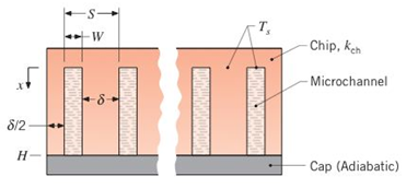
Consider the microchannel cooling arrangement ofProblem 8.107. However, instead of assuming theentire chip and cap to be at a uniform temperature.adopt a more conservative (and realistic) approach thatprescribes a temperature of T s = 350 K at the base ofthe channels ( x = 0 ) and allows for a decrease in temperature with increasing x along the side walls of eachchannel. (a) For the operating conditions prescribed in Problem 8.107 and a chip thermal conductivity of k c h = 140 W/m ⋅ K , determine the water outlet temperature and the chip power dissipation. Heat transfer from the sides of the chip to the surroundings and from the side walls of a channel to the cap may be neglected. Note that the spacing between channels. δ = S − W , is twice the spacing between the side wall of an outer channel and the outer surface of the chip. The channel pitch is S = L / N , where L = 1 0 mm is the chip width and N = 5 0 is the number of channels (b) The channel geometry prescribed in Problem 8.107 and considered in part (a) is not optimized, and larger heat rates may be dissipated by adjusting related dimensions. Consider the effect of reducing the pitch to a value of S = 100 μ m . while retaining a width of W = 50 μ m and a flow rate per channel of m 1 = 10 − 4 kg/s.
Consider the microchannel cooling arrangement ofProblem 8.107. However, instead of assuming theentire chip and cap to be at a uniform temperature.adopt a more conservative (and realistic) approach thatprescribes a temperature of T s = 350 K at the base ofthe channels ( x = 0 ) and allows for a decrease in temperature with increasing x along the side walls of eachchannel. (a) For the operating conditions prescribed in Problem 8.107 and a chip thermal conductivity of k c h = 140 W/m ⋅ K , determine the water outlet temperature and the chip power dissipation. Heat transfer from the sides of the chip to the surroundings and from the side walls of a channel to the cap may be neglected. Note that the spacing between channels. δ = S − W , is twice the spacing between the side wall of an outer channel and the outer surface of the chip. The channel pitch is S = L / N , where L = 1 0 mm is the chip width and N = 5 0 is the number of channels (b) The channel geometry prescribed in Problem 8.107 and considered in part (a) is not optimized, and larger heat rates may be dissipated by adjusting related dimensions. Consider the effect of reducing the pitch to a value of S = 100 μ m . while retaining a width of W = 50 μ m and a flow rate per channel of m 1 = 10 − 4 kg/s.
Solution Summary: The author describes the water outlet temperature, chip power dissipation, and thermal conductivity of the chip. The expression for the hydraulic diameter is given as, mathrmRe_D
Consider the microchannel cooling arrangement ofProblem 8.107. However, instead of assuming theentire chip and cap to be at a uniform temperature.adopt a more conservative (and realistic) approach thatprescribes a temperature of
T
s
=
350
K at the base ofthe channels (
x
=
0
) and allows for a decrease in temperature with increasing x along the side walls of eachchannel.
(a) For the operating conditions prescribed in Problem 8.107 and a chip thermal conductivity of
k
c
h
=
140
W/m
⋅
K
, determine the water outlet temperature and the chip power dissipation. Heat transfer from the sides of the chip to the surroundings and from the side walls of a channel to the cap may be neglected. Note that the spacing between channels.
δ
=
S
−
W
, is twice the spacing between the side wall of an outer channel and the outer surface of the chip. The channel pitch is
S
=
L
/
N
, where
L
=
1
0
mm
is the chip width and
N
=
5
0
is the number of channels
(b) The channel geometry prescribed in Problem 8.107 and considered in part (a) is not optimized, and larger heat rates may be dissipated by adjusting related dimensions. Consider the effect of reducing the pitch to a value of
S
=
100
μ
m
. while retaining a width of
W
=
50
μ
m
and a flow rate per channel of
m
1
=
10
−
4
kg/s.
Can you provide steps and an explaination on how the height value to calculate the Pressure at point B is (-5-3.5) and the solution is 86.4kPa.
PROBLEM 3.46
The solid cylindrical rod BC of length L = 600
mm is attached to the rigid lever AB of length a
= 380 mm and to the support at C. When a 500
N force P is applied at A, design specifications
require that the displacement of A not exceed
25 mm when a 500 N force P is applied at A
For the material indicated determine the
required diameter of the rod.
Aluminium: Tall = 65 MPa, G = 27 GPa.
A
Find the equivalent mass of the rocker arm assembly with respect to the x coordinate.
k₁
mi
m2
k₁
Need a deep-dive on the concept behind this application? Look no further. Learn more about this topic, mechanical-engineering and related others by exploring similar questions and additional content below.


 Principles of Heat Transfer (Activate Learning wi...Mechanical EngineeringISBN:9781305387102Author:Kreith, Frank; Manglik, Raj M.Publisher:Cengage Learning