
Concept explainers
Videos
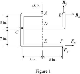
The 48-lb load can be moved along the line of action shown and applied at A, D, or E. Determine the components of the reactions at B and F if the 48-lb load is applied (a) at A, (b) at D, (c) at E.
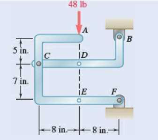
Fig. P6.88 and P6.89
SOLUTION
Free body: Entire frame:
The following analysis is valid for (a), (b) and (c) since the position of the load along its line of action is immaterial.
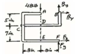
 ∑MF = 0: (48 lb)(8 in.) − Bx (12 in.) = 0
Bx = 32 lb Bx = 32 lb →
 ∑Fx = 0: 32 lb + Fx = 0
Fx = −32 lb Fx = 32 lb ←
+↑ ∑Fy = 0: By + Fy − 48 lb = 0 (1)
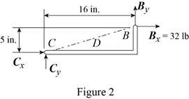
a) Load applied at A.
Free body: Member CDB
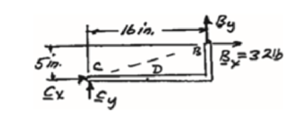
CDB is a two-force member. Thus, the reaction at B must be directed along BC.
From Eq. (1): 10 lb + Fy − 48 lb = 0
Fy = 38 lb Fy = 38 lb ↑
Thus reactions are:
Bx = 32.0 lb →, By = 10.00 lb ↑
Fx = 32.0 lb ←, Fy = 38.00 lb ↑
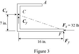
(b) Load applied at D.
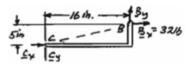
Free body: Member ACF.
ACF is a two-force member. Thus, the reaction at F must be directed along CF.
From Eq. (1): By + 14 lb – 48 lb = 0
By = 34 lb, By = 34 lb ↑
Thus, reactions are:
Bx = 32.0 lb ←, By = 34.00 lb ↑
Fx = 32.0 lb →, Fy = 14.00 lb ↑
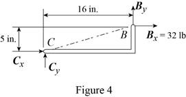
(c) Load applied at E.
Free body: Member CDB.
This is the same free body as in Part (a).
Reactions are same as (a)
(a)
The components of reaction at
Answer to Problem 6.88P
The components of reaction at
Explanation of Solution
The arrangement is shown in Fig. P6.88. The free-body diagram of the entire frame is given in Figure 1.
Write the expressions for equilibrium for the given system using the conditions on moments
The counter clockwise moments at
The sum of
The sum of
The load is applied at
Conclusion:
Apply the condition in equation (I) to the free-body diagram in Figure 1 and solve for
Apply the condition in equation (II) to the free-body diagram in Figure 1 and solve for
Apply the condition in equation (III) to the free-body diagram in Figure 1.
From the free-body diagram in Figure 2, write the expression connecting the components of the reaction
Substitute
Substitute
Therefore, the components of reaction at
(b)
The components of reaction at
Answer to Problem 6.88P
The components of reaction at
Explanation of Solution
The
The load is applied at
Conclusion:
From the free-body diagram in Figure 3, write the expression connecting the components of the reaction
Substitute
Substitute
Therefore, the components of reaction at
(c)
The components of reaction at
Answer to Problem 6.88P
The components of reaction at
Explanation of Solution
The
The load is applied at
Conclusion:
The free-body diagram of the member
Therefore, the components of reaction at
Want to see more full solutions like this?
Chapter 6 Solutions
Vector Mechanics for Engineers: Statics, 11th Edition


- 6. A part of the structure for a factory automation system is a beam that spans 30.0 in as shown in Figure P5-6. Loads are applied at two points, each 8.0 in from a support. The left load F₁ = 1800 lb remains constantly applied, while the right load F₂ = 1800 lb is applied and removed fre- quently as the machine cycles. Evaluate the beam at both B and C. A 8 in F₁ = 1800 lb 14 in F2 = 1800 lb 8 in D RA B C 4X2X1/4 Steel tube Beam cross section RDarrow_forward30. Repeat Problem 28, except using a shaft that is rotating and transmitting a torque of 150 N⚫m from the left bear- ing to the middle of the shaft. Also, there is a profile key- seat at the middle under the load.arrow_forward28. The shaft shown in Figure P5-28 is supported by bear- ings at each end, which have bores of 20.0 mm. Design the shaft to carry the given load if it is steady and the shaft is stationary. Make the dimension a as large as pos- sible while keeping the stress safe. Determine the required d = 20mm D = ? R = ?| 5.4 kN d=20mm Length not to scale -a = ?- +а= a = ? + -125 mm- -250 mm- FIGURE P5-28 (Problems 28, 29, and 30)arrow_forward
- 12. Compute the estimated actual endurance limit for SAE 4130 WQT 1300 steel bar with a rectangular cross sec- tion of 20.0 mm by 60 mm. It is to be machined and subjected to repeated and reversed bending stress. A reli- ability of 99% is desired.arrow_forward28. The shaft shown in Figure P5-28 is supported by bear- ings at each end, which have bores of 20.0 mm. Design the shaft to carry the given load if it is steady and the shaft is stationary. Make the dimension a as large as pos- sible while keeping the stress safe. Determine the required d = 20mm D = ? R = ?| 5.4 kN d=20mm Length not to scale -a = ?- +а= a = ? + -125 mm- -250 mm- FIGURE P5-28 (Problems 28, 29, and 30)arrow_forward2. A strut in a space frame has a rectangular cross section of 10.0 mm by 30.0 mm. It sees a load that varies from a tensile force of 20.0 kN to a compressive force of 8.0 kN.arrow_forward
- find stress at Qarrow_forwardI had a theoretical question about attitude determination. In the attached images, I gave two axis and angles. The coefficient of the axes are the same and the angles are the same. The only difference is the vector basis. Lets say there is a rotation going from n hat to b hat. Then, you introduce a intermediate rotation s hat. So, I want to know if the DCM produced from both axis and angles will be the same or not. Does the vector basis affect the numerical value of the DCM? The DCM formula only cares about the coefficient of the axis and the angle. So, they should be the same right?arrow_forward3-15. A small fixed tube is shaped in the form of a vertical helix of radius a and helix angle y, that is, the tube always makes an angle y with the horizontal. A particle of mass m slides down the tube under the action of gravity. If there is a coefficient of friction μ between the tube and the particle, what is the steady-state speed of the particle? Let y γ 30° and assume that µ < 1/√3.arrow_forward
- The plate is moving at 0.6 mm/s when the force applied to the plate is 4mN. If the surface area of the plate in contact with the liquid is 0.5 m^2, deterimine the approximate viscosity of the liquid, assuming that the velocity distribution is linear.arrow_forward3-9. Given that the force acting on a particle has the following components: Fx = −x + y, Fy = x − y + y², F₂ = 0. Solve for the potential energy V. -arrow_forward2.5 (B). A steel rod of cross-sectional area 600 mm² and a coaxial copper tube of cross-sectional area 1000 mm² are firmly attached at their ends to form a compound bar. Determine the stress in the steel and in the copper when the temperature of the bar is raised by 80°C and an axial tensile force of 60 kN is applied. For steel, E = 200 GN/m² with x = 11 x 10-6 per °C. E = 100 GN/m² with α = 16.5 × 10⁻⁶ For copper, per °C. [E.I.E.] [94.6, 3.3 MN/m².]arrow_forward
 International Edition---engineering Mechanics: St...Mechanical EngineeringISBN:9781305501607Author:Andrew Pytel And Jaan KiusalaasPublisher:CENGAGE L