
Concept explainers
Videos
The truss shown consists of nine members and is support by a ball-and-socket at B, a short link at C, and two short links at D. (a) Check that this truss is a simple truss, that completely constrained, and that the reactions at its suppo are statically determinate. (b) Determine the force in each member for P = (−1200 N)j and Q = 0.
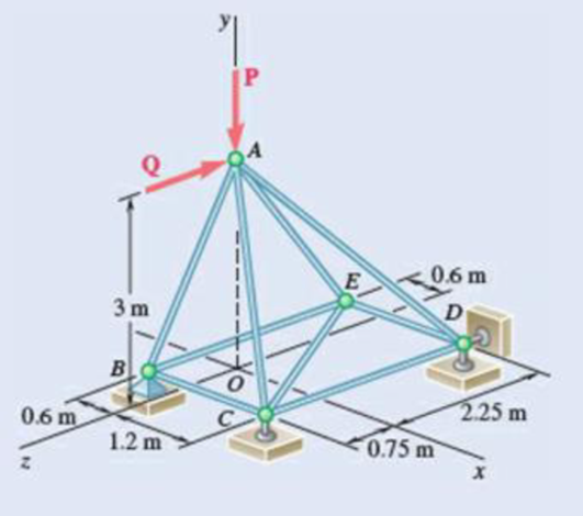
Fig. P6.39
(a)
Verify that the truss is a simple truss, completely constrained, and the reactions at the supports are statically determinate.
Answer to Problem 6.39P
The reactions at supports B, C, and D is
Explanation of Solution
Given information:
The value of the force P is
The value of the force Q is zero.
Calculation:
Show the free-body diagram of the truss as in Figure 1.
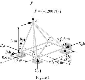
Find the vector coordinates by taking moment about point B.
Equate the coefficients of i to zero.
Equate the coefficients of j to zero.
Equate the coefficients of k to zero.
Substitute 300 N for
Resolve the force components in y-axis.
Substitute 300 N for
The unknown reactions can be calculated with the equilibrium equations. Therefore, the truss is statically determinate, completely constrained and simple truss.
Thus, the reactions at supports B, C, and D is
(b)
Find the force in each member of the truss.
Answer to Problem 6.39P
The force in the member AB is
The force in the member BC is
The force in the member BE is
The force in the member AC is
The force in the member CE is
The force in the member CD is
The force in the member AD is
The force in the member DE is
The force in the member AE is
Explanation of Solution
Show the free-body diagram of the joint B as in Figure 2.
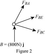
Resolve the force components as follows;
Write the vector value of
Find the scalar quantity of BA using the relation.
Find the force in the member AB as follows;
Substitute
Find the force in the member BC as follows;
Find the force in the member BE as follows;
Equate the coefficients of j to zero.
Equate the coefficients of i to zero.
Substitute –840 N for
Equate the coefficients of k to zero.
Substitute –840 N for
Therefore,
The force in the member AB is
The force in the member BC is
The force in the member BE is
Show the free-body diagram of the joint C as in Figure 3.
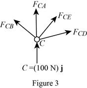
Resolve the force components as follows;
Write the vector value of
Find the scalar quantity of CA using the relation.
Find the force in the member AC as follows;
Substitute
Find the force in the member CB as follows;
Find the force in the member CD as follows;
Write the vector value of
Find the scalar quantity of CE using the relation.
Find the force in the member CE as follows;
Substitute
Equate the coefficients of j to zero.
Equate the coefficients of i to zero.
Substitute –110.6 N for
Equate the coefficients of k to zero.
Substitute –110.6 N for
Therefore,
The force in the member AC is
The force in the member CE is
The force in the member CD is
Show the free-body diagram of the joint D as in Figure 4.
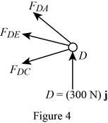
Resolve the force components as follows;
Write the vector value of
Find the scalar quantity of DA using the relation.
Find the force in the member AD as follows;
Substitute
Find the force in the member DC as follows;
Find the force in the member DE as follows;
Equate the coefficients of j to zero.
Equate the coefficients of i to zero.
Substitute –394 N for
Therefore,
The force in the member AD is
The force in the member DE is
Show the free-body diagram of the joint E as in figure 5.
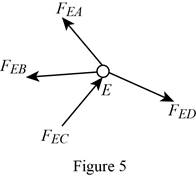
The member AE is not in the xz plane.
Therefore, the force in the member AE is
Want to see more full solutions like this?
Chapter 6 Solutions
Vector Mechanics for Engineers: Statics, 11th Edition


- In figure A, the homogeneous rod of constant cross section is attached to unyielding supports. In figure B, a homogeneous bar with a cross-sectional area of 600 mm2 is attached to rigid supports. The bar carries the axial loads P1 = 20 kN and P2 = 60 kN, as shown.1. In figure A, derive the expression that calculates the reaction R1 in terms of P, and the given dimensions.2. In figure B, calculate the reaction (kN) at A.3. In figure B, calculate the maximum axial stress (MPa) in the rod.arrow_forward(Read image)arrow_forward(Read Image)arrow_forward
- M16x2 grade 8.8 bolts No. 25 C1- Q.2. The figure is a cross section of a grade 25 cast-iron pressure vessel. A total of N, M16x2.0 grade 8.8 bolts are to be used to resist a separating force of 160 kN. (a) Determine ks, km, and C. (b) Find the number of bolts required for a load factor of 2 where the bolts may be reused when the joint 19 mm is taken apart. (c) with the number of bolts obtained in (b), determine the realized load factor for overload, the yielding factor of safety, and the separation factor of safety. 19 mmarrow_forwardProblem4. The thin uniform disk of mass m = 1-kg and radius R = 0.1m spins about the bent shaft OG with the angular speed w2 = 20 rad/s. At the same time, the shaft rotates about the z-axis with the angular speed 001 = 10 rad/s. The angle between the bent portion of the shaft and the z-axis is ẞ = 35°. The mass of the shaft is negligible compared to the mass of the disk. a. Find the angular momentum of the disk with respect to point G, based on the axis orientation as shown. Include an MVD in your solution. b. Find the angular momentum of the disk with respect to point O, based on the axis orientation as shown. (Note: O is NOT the center of fixed-point rotation.) c. Find the kinetic energy of the assembly. z R R 002 2R x Answer: H = -0.046ĵ-0.040 kg-m²/sec Ho=-0.146-0.015 kg-m²/sec T 0.518 N-m =arrow_forwardProblem 3. The assembly shown consists of a solid sphere of mass m and the uniform slender rod of the same mass, both of which are welded to the shaft. The assembly is rotating with angular velocity w at a particular moment. Find the angular momentum with respect to point O, in terms of the axes shown. Answer: Ñ。 = ½mc²wcosßsinßĵ + (}{mr²w + 2mb²w + ½ mc²wcos²ß) k 3 m r b 2 C لا marrow_forward
- I have Euler parameters that describe the orientation of N relative to Q, e = -0.7071*n3, e4 = 0.7071. I have Euler parameters that describe the orientation of U relative to N, e = -1/sqrt(3)*n1, e4 = sqrt(2/3). After using euler parameter rule of successive rotations, I get euler parameters that describe the orientation of U relative to Q, e = -0.4082*n1 - 0.4082*n2 - 0.5774*n3. I need euler parameters that describe the orientation of U relative to Q in vector basis of q instead of n. How do I get that?arrow_forwardDescribe at least 4 processes in engineering where control charts are (or should be) appliedarrow_forwardDescribe at least two (2) processes where control charts are (or should be) applied.arrow_forward
 International Edition---engineering Mechanics: St...Mechanical EngineeringISBN:9781305501607Author:Andrew Pytel And Jaan KiusalaasPublisher:CENGAGE L