
Concept explainers
Videos
The force in each of the members of the truss for the given loading.
Answer to Problem 6.38P
The force in member
Explanation of Solution
The free-body diagram of the entire truss is shown in figure 1.
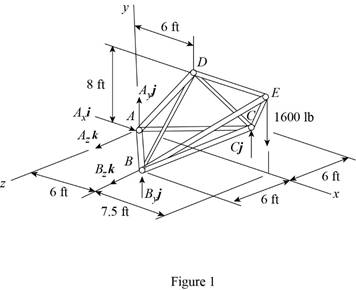
Refer to figure 1 and use symmetry.
Here,
The
Here,
Sum of the moments must be equal to zero.
Here,
Write the equation for
Here,
Put the above equation in equation (I).
Write the expression for the reaction at the point A.
Here,
Substitute
Use symmetry.
Here,
The
Here,
Write the expression for
Put the above equation in equation (II).
Write the expression for the reaction at the point A.
Here,
Substitute
Consider the free body
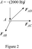
The net force must be equal to zero.
Here,
Write the expression for
Put the above equation in equation (III).
Here,
Write the expression for
Here,
Write the expression for
Here,
Write the expression for
Here,
Put equations (V), (VI) and (VII) in equation (IV).
Factorize
Equate the coefficient of
Equate the coefficient of
Equate the coefficient of
Put equation (X) in equation (IX).
Substitute
Put the above equation in equation (X).
Consider the free-body joint B. The free-body diagram of joint B is shown in figure 3.
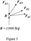
Refer to figure (3) and write the expression for the forces.
Here,
Substitute
Write the expression for
Here,
Write the expression for
Here,
Write the expression for
Here,
Substitute
Write the expression for
Put the above equation in equation (III).
Put equations (XI), (XII), (XIII) , (XIV) and substitute
Equate the coefficient of
Equate the coefficient of
Substitute
Equate the coefficient of
Substitute
Use symmetry.
Here,
Substitute
Consider the free body joint D. The free body diagram is shown in figure 4.
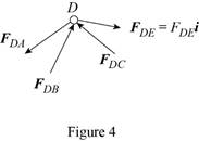
Write the expression for
Put the above equation in equation (III).
Only
Equate the coefficient of
Substitute
Conclusion:
Thus, the force in member
Want to see more full solutions like this?
Chapter 6 Solutions
Vector Mechanics for Engineers: Statics, 11th Edition


- PROBLEM 3.46 The solid cylindrical rod BC of length L = 600 mm is attached to the rigid lever AB of length a = 380 mm and to the support at C. When a 500 N force P is applied at A, design specifications require that the displacement of A not exceed 25 mm when a 500 N force P is applied at A For the material indicated determine the required diameter of the rod. Aluminium: Tall = 65 MPa, G = 27 GPa. Aarrow_forwardFind the equivalent mass of the rocker arm assembly with respect to the x coordinate. k₁ mi m2 k₁arrow_forward2. Figure below shows a U-tube manometer open at both ends and containing a column of liquid mercury of length l and specific weight y. Considering a small displacement x of the manometer meniscus from its equilibrium position (or datum), determine the equivalent spring constant associated with the restoring force. Datum Area, Aarrow_forward
- 1. The consequences of a head-on collision of two automobiles can be studied by considering the impact of the automobile on a barrier, as shown in figure below. Construct a mathematical model (i.e., draw the diagram) by considering the masses of the automobile body, engine, transmission, and suspension and the elasticity of the bumpers, radiator, sheet metal body, driveline, and engine mounts.arrow_forward3.) 15.40 – Collar B moves up at constant velocity vB = 1.5 m/s. Rod AB has length = 1.2 m. The incline is at angle = 25°. Compute an expression for the angular velocity of rod AB, ė and the velocity of end A of the rod (✓✓) as a function of v₂,1,0,0. Then compute numerical answers for ȧ & y_ with 0 = 50°.arrow_forward2.) 15.12 The assembly shown consists of the straight rod ABC which passes through and is welded to the grectangular plate DEFH. The assembly rotates about the axis AC with a constant angular velocity of 9 rad/s. Knowing that the motion when viewed from C is counterclockwise, determine the velocity and acceleration of corner F.arrow_forward
 International Edition---engineering Mechanics: St...Mechanical EngineeringISBN:9781305501607Author:Andrew Pytel And Jaan KiusalaasPublisher:CENGAGE L