
Vector Mechanics for Engineers: Statics, 11th Edition
11th Edition
ISBN: 9780077687304
Author: Ferdinand P. Beer, E. Russell Johnston Jr., David Mazurek
Publisher: McGraw-Hill Education
expand_more
expand_more
format_list_bulleted
Videos
Textbook Question
Chapter 6.3, Problem 6.78P
Determine the components of all forces acting on member ABCD of the assembly shown.
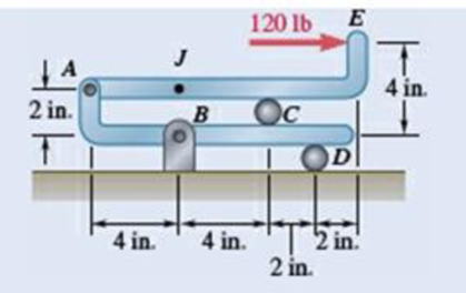
Fig. P6.78
Expert Solution & Answer
Want to see the full answer?
Check out a sample textbook solution
Students have asked these similar questions
B
60 ft
WAB
AB
30%
:
The crane's telescopic boom rotates with the angular velocity w = 0.06 rad/s and
angular acceleration a = 0.07 rad/s². At the same instant, the boom is extending
with a constant speed of 0.8 ft/s, measured relative to the boom. Determine the
magnitude of the acceleration of point B at this instant.
The motion of peg P is constrained by the lemniscate curved
slot in OB and by the slotted arm OA. (Figure 1)
If OA rotates counterclockwise with a constant angular velocity of 0 = 3 rad/s, determine the magnitude of the velocity of peg P at 0 = 30°.
Express your answer to three significant figures and include the appropriate units.
Determine the magnitude of the acceleration of peg P at 0 = 30°.
Express your answer to three significant figures and include the appropriate units.
0
(4 cos 2 0)m²
B
A
5: The structure shown was designed to support a30-kN load. It consists of a boom AB with a 30 x 50-mmrectangular cross section and a rod BC with a 20-mm-diametercircular cross section. The boom and the rod are connected bya pin at B and are supported by pins and brackets at A and C,respectively.1. Calculate the normal stress in boom AB and rod BC,indicate if in tension or compression.2. Calculate the shear stress of pins at A, B and C.3. Calculate the bearing stresses at A in member AB,and in the bracket.
Chapter 6 Solutions
Vector Mechanics for Engineers: Statics, 11th Edition
Ch. 6.1 - 6.1 through 6.8 Using the method of joints,...Ch. 6.1 - Prob. 6.2PCh. 6.1 - Prob. 6.3PCh. 6.1 - 6.1 through 6.8 Using the method of joints,...Ch. 6.1 - 6.1 through 6.8 Using the method of joints,...Ch. 6.1 - Using the method of joints, determine the force in...Ch. 6.1 - 6.1 through 6.8 Using the method of joints,...Ch. 6.1 - Prob. 6.8PCh. 6.1 - 6.9 and 6.10 Determine the force in each member of...Ch. 6.1 - 6.9 and 6.10 Determine the force in each member of...
Ch. 6.1 - Determine the force in each member of the Gambrel...Ch. 6.1 - Determine the force in each member of the Howe...Ch. 6.1 - Using the method of joints, determine the force in...Ch. 6.1 - 6.14 Determine the force in each member of the...Ch. 6.1 - Determine the force in each member of the Warren...Ch. 6.1 - Solve Problem 6.15 assuming that the load applied...Ch. 6.1 - Determine the force in each member of the Pratt...Ch. 6.1 - The truss shown is one of several supporting an...Ch. 6.1 - Determine the force in each member of the Pratt...Ch. 6.1 - Solve Problem 6.19 assuming that the load applied...Ch. 6.1 - Determine the force in each of the members located...Ch. 6.1 - Determine the force in member DE and in each of...Ch. 6.1 - Determine the force in each of the members located...Ch. 6.1 - The portion of truss shown represents the upper...Ch. 6.1 - For the tower and loading of Prob. 6.24 and...Ch. 6.1 - Solve Problem 6.24 assuming that the cables...Ch. 6.1 - Determine the force in each member of the truss...Ch. 6.1 - Determine the force in each member of the truss...Ch. 6.1 - Prob. 6.29PCh. 6.1 - 6.30 Determine whether the trusses of Probs....Ch. 6.1 - 6.31 For the given loading. determine the...Ch. 6.1 - For the given loading, determine the zero-force...Ch. 6.1 - For the given loading, determine the zero-force...Ch. 6.1 - Determine the zero-force members in the truss of...Ch. 6.1 - The truss shown consists of six members and is...Ch. 6.1 - The truss shown consists of six members and is...Ch. 6.1 - The truss shown consists of six members and is...Ch. 6.1 - Prob. 6.38PCh. 6.1 - The truss shown consists of nine members and is...Ch. 6.1 - Solve Prob. 6.39 for P = 0 and Q = (900 N)k. 6.39...Ch. 6.1 - The truss shown consists of 18 members and is...Ch. 6.1 - The truss shown consists of 18 members and is...Ch. 6.2 - 6 .43 A Mansard roof truss is loaded as shown....Ch. 6.2 - Prob. 6.44PCh. 6.2 - Determine the force in members BD and CD of the...Ch. 6.2 - Determine the force in members DF and DG of the...Ch. 6.2 - 6.47 Determine the force in members CD and DF of...Ch. 6.2 - Prob. 6.48PCh. 6.2 - Determine the force in members CD and DF of the...Ch. 6.2 - Determine the force in members CE and EF of the...Ch. 6.2 - Determine the force in members DE and DF of the...Ch. 6.2 - Determine the force in members EG and EF of the...Ch. 6.2 - Determine the force in members DF and DE of the...Ch. 6.2 - Determine the force in members CD and CE of the...Ch. 6.2 - Prob. 6.55PCh. 6.2 - 6.56 A monosloped roof truss is loaded as shown....Ch. 6.2 - A Howe scissors roof truss is loaded as shown....Ch. 6.2 - A Howe scissors roof truss is loaded as shown....Ch. 6.2 - Determine the force in members AD, CD, and CE of...Ch. 6.2 - Determine the force in members DG, FG, and FH of...Ch. 6.2 - 6.61 Determine the force in members DC and FI of...Ch. 6.2 - Prob. 6.62PCh. 6.2 - Prob. 6.63PCh. 6.2 - Prob. 6.64PCh. 6.2 - The diagonal members in the center panels of the...Ch. 6.2 - The diagonal members in the center panels of the...Ch. 6.2 - The diagonal members in the center panels of the...Ch. 6.2 - Solve Prob. 6.67 assuming that the 9-kip load has...Ch. 6.2 - Classify each of the structures shown as...Ch. 6.2 - Classify each of the structures shown as...Ch. 6.2 - 6.70 through 6.74 classify as determinate or...Ch. 6.2 - 6.70 through 6.74 classify as determinate or...Ch. 6.2 - 6.70 through 6.74 classify as determinate or...Ch. 6.2 - 6.70 through 6.74 classify as determinate or...Ch. 6.3 - For the frame and loading shown, draw the...Ch. 6.3 - For the frame and loading shown, draw the...Ch. 6.3 - Draw the free-body diagram(s) needed to determine...Ch. 6.3 - Knowing that the pulley has a radius of 0.5 m,...Ch. 6.3 - 6.75 and 6.76 Determine the force in member BD and...Ch. 6.3 - 6.75 and 6.76 Determine the force in member BD and...Ch. 6.3 - For the frame and loading shown, determine the...Ch. 6.3 - Determine the components of all forces acting on...Ch. 6.3 - Prob. 6.79PCh. 6.3 - Prob. 6.80PCh. 6.3 - Determine the components of all forces acting on...Ch. 6.3 - Determine the components of all forces acting on...Ch. 6.3 - Determine the components of the reactions at A and...Ch. 6.3 - Determine the components of the reactions at D and...Ch. 6.3 - Determine the components of the reactions at A and...Ch. 6.3 - Determine the components of the reactions at A and...Ch. 6.3 - Prob. 6.87PCh. 6.3 - The 48-lb load can be moved along the line of...Ch. 6.3 - The 48-lb load is removed and a 288-lb in....Ch. 6.3 - (a) Show that, when a frame supports a pulley at...Ch. 6.3 - Knowing that each pulley has a radius of 250 mm,...Ch. 6.3 - Knowing that the pulley has a radius of 75 mm,...Ch. 6.3 - 6.93 A 3-ft-diameter pipe is supported every 16 ft...Ch. 6.3 - Prob. 6.94PCh. 6.3 - A trailer weighing 2400 lb is attached to a...Ch. 6.3 - In order to obtain a better weight distribution...Ch. 6.3 - The cab and motor units of the front-end loader...Ch. 6.3 - Solve Problem 6.97 assuming that the 75-kN load...Ch. 6.3 - Knowing that P = 90 lb and Q = 60 lb, determine...Ch. 6.3 - Knowing that P = 90 lb and Q = 60 lb, determine...Ch. 6.3 - For the frame and loading shown, determine the...Ch. 6.3 - For the frame and loading shown, determine the...Ch. 6.3 - 6.103 For the frame and loading shown, determine...Ch. 6.3 - Prob. 6.104PCh. 6.3 - For the frame and loading shown, determine the...Ch. 6.3 - Solve Prob. 6.105 assuming that the 6-kN load has...Ch. 6.3 - The axis of the three-hinge arch ABC is a parabola...Ch. 6.3 - The axis of the three-hinge arch ABC is a parabola...Ch. 6.3 - 6.109 and 6.110 Neglecting the effect of friction...Ch. 6.3 - and 6.110 Neglecting the effect of friction at the...Ch. 6.3 - 6.111, 6.112, and 6.113 Members ABC and CDE are...Ch. 6.3 - 6.111, 6.112, and 6.113 Members ABC and CDE are...Ch. 6.3 - 6.111, 6.112, and 6.113 Members ABC and CDE are...Ch. 6.3 - Prob. 6.114PCh. 6.3 - Solve Prob. 6.112 assuming that the force P is...Ch. 6.3 - Prob. 6.116PCh. 6.3 - Four beams, each with a length of 2a, are nailed...Ch. 6.3 - Four beams, each with a length of 3a, are held...Ch. 6.3 - 6.119 through 6.121 Each of the frames shown...Ch. 6.3 - 6.119 through 6.121 Each of the frames shown...Ch. 6.3 - 6.119 through 6.121 Each of the frames shown...Ch. 6.4 - An 84-lb force is applied to the toggle vise at C....Ch. 6.4 - For the system and loading shown, draw the...Ch. 6.4 - A small barrel weighing 60 lb is lifted by a pair...Ch. 6.4 - The position of member ABC is controlled by the...Ch. 6.4 - The shear shown is used to cut and trim...Ch. 6.4 - A 100-lb force directed vertically downward is...Ch. 6.4 - Prob. 6.124PCh. 6.4 - The control rod CE passes through a horizontal...Ch. 6.4 - Solve Prob. 6.125 when (a) = 0, (b) = 6. Fig....Ch. 6.4 - The press shown is used to emboss a small seal at...Ch. 6.4 - The press shown is used to emboss a small seal at...Ch. 6.4 - The pin at B is attached to member ABC and can...Ch. 6.4 - The pin at B is attached to member ABC and can...Ch. 6.4 - Arm ABC is connected by pins to a collar at B and...Ch. 6.4 - Arm ABC is connected by pins to a collar at B and...Ch. 6.4 - The Whitworth mechanism shown is used to produce a...Ch. 6.4 - Solve Prob. 6.133 when (a) = 60, (b) = 90. Fig....Ch. 6.4 - Prob. 6.135PCh. 6.4 - 6.135 and 6.136 Two rods are connected by a...Ch. 6.4 - 6.137 and 6.138 Rod CD is attached to the collar D...Ch. 6.4 - 6.137 and 6.138 Rod CD is attached to the collar D...Ch. 6.4 - Two hydraulic cylinders control the position of...Ch. 6.4 - Two hydraulic cylinders control the position of...Ch. 6.4 - Prob. 6.141PCh. 6.4 - Prob. 6.142PCh. 6.4 - 6.143 The tongs shown are used to apply a total...Ch. 6.4 - Prob. 6.144PCh. 6.4 - The pliers shown are used to grip a...Ch. 6.4 - Prob. 6.146PCh. 6.4 - In using the bolt cutter shown, a worker applies...Ch. 6.4 - Prob. 6.148PCh. 6.4 - and 6.150 Determine the force P that must be...Ch. 6.4 - and 6.150 Determine the force P that must be...Ch. 6.4 - Because the brace shown must remain in position...Ch. 6.4 - The specialized plumbing wrench shown is used in...Ch. 6.4 - Prob. 6.153PCh. 6.4 - Prob. 6.154PCh. 6.4 - The telescoping arm ABC is used to provide an...Ch. 6.4 - The telescoping arm ABC of Prob. 6.155 can be...Ch. 6.4 - The motion of the backhoe bucket shown is...Ch. 6.4 - Solve Prob. 6.157 assuming that the 2-kip force P...Ch. 6.4 - Prob. 6.159PCh. 6.4 - In the planetary gear system shown, the radius of...Ch. 6.4 - Two shafts AC and CF, which lie in the vertical xy...Ch. 6.4 - Two shafts AC and CF, which lie in the vertical xy...Ch. 6.4 - The large mechanical tongs shown are used to grab...Ch. 6 - Using the method of joints, determine the force in...Ch. 6 - Using the method of joints, determine the force in...Ch. 6 - A stadium roof truss is loaded as shown. Determine...Ch. 6 - A stadium roof truss is loaded as shown. Determine...Ch. 6 - Determine the components of all forces acting on...Ch. 6 - Determine the components of the reactions at A and...Ch. 6 - Knowing that the pulley has a radius of 50 mm,...Ch. 6 - For the frame and loading shown, determine the...Ch. 6 - For the frame and loading shown, determine the...Ch. 6 - Water pressure in the supply system exerts a...Ch. 6 - A couple M with a magnitude of 1.5 kNm is applied...Ch. 6 - The compound-lever pruning shears shown can be...
Knowledge Booster


Learn more about
Need a deep-dive on the concept behind this application? Look no further. Learn more about this topic, mechanical-engineering and related others by exploring similar questions and additional content below.Similar questions
- 4: The boom AC is a 4-in. square steel tube with a wallthickness of 0.25 in. The boom is supported by the 0.5-in.-diameter pinat A, and the 0.375-in.-diameter cable BC. The working stresses are 25ksi for the cable, 18 ksi for the boom, and 13.6 ksi for shear in the pin.Neglect the weight of the boom.1. Calculate the maximum value of P (kips) based on boom compression and the maximum value of P (kips) based on tension in the cable.2. Calculate the maximum value of P (kips) based on shear in pin.arrow_forward3: A steel strut S serving as a brace for a boat hoist transmits a compressive force P = 54 kN to the deck of a pier as shown in Fig. STR-08. The strut has a hollow square cross section with a wall thickness t =12mm and the angle θ between the strut and the horizontal is 40°. A pin through the strut transmits the compressive force from the strut to two gusset plates G that are welded to the base plate B. Four anchor bolts fasten the base plate to the deck. The diameter of the pin is 20mm, the thickness of the gusset plates is 16mm, the thickness of the base plate is 8mm, and the diameter of the anchor bolts is 12mm. Disregard any friction between the base plate and the deck.1. Determine the shear stress in the pin, in MPa and the shear stress in the anchor bolts, in MPa.2. Determine the bearing stress in the strut holes, in MPa.arrow_forward1. In the figure, the beam, W410x67, with 9 mm web thicknesssubjects the girder, W530x109 with 12 mm web thickness to a shear load,P (kN). 2L – 90 mm × 90 mm × 6 mm with bolts frame the beam to thegirder.Given: S1 = S2 = S5 = 40 mm; S3 = 75 mm; S4 = 110 mmAllowable Stresses are as follows:Bolt shear stress, Fv = 125 MPaBolt bearing stress, Fp = 510 MPa1. Determine the allowable load, P (kN), based on the shearcapacity of the 4 – 25 mm diameter bolts (4 – d1) and calculate the allowable load, P (kN), based on bolt bearing stress on the web of the beam.2. If P = 450 kN, determine the minimum diameter (mm) of 4 – d1based on allowable bolt shear stress and bearing stress of thebeam web.arrow_forward
- 6: The 6-kN load P is supported by two wooden members of 75 x 125-mm uniform cross section that are joined by the simple glued scarf splice shown.1. Calculate the normal stress in the glue, in MPa.2. Calculate the shear stress in the glue, in MPa.arrow_forwardUsing Matlab calculate the following performance characteristics for a Tesla Model S undergoing the 4506 drive cycle test Prated Trated Ebat 80kW 254 Nm 85kWh/1645kg MUEH A rwheel 0.315M 133.3 C 0.491 Ng ng 7g 8.190.315 8.19 0.315 7ed= 85% Ebpt 35-956 DRIVE AXLE Ebfb chę =85% V Minverter H/A Battery Charger En AC Pry 9) required energy output from the motor to drive this cycle Cassume no regenerative braking) b) range of the Tesla Model S for this drive cycle (assume no regenerative breaking c) estimated mpge cycle of the Tesla Model S for this drive Cassume no regenerative breaking) d) Recalculate parts abc now assuming you can regenerate returns correctly due to inefficiency. from braking. Be careful to handle the diminishing energy braking makes in terms of required e) Quantify the percentage difference that regenerative required energy, range and mpge, DI L Ta a ra OLarrow_forwardHW.5.1 Determine the vertical displacement of joint C on the truss as shown by using Castigliano's theorem. Let E = 200(109) GPa and A = 300 mm² 4 m E 20 kN 3 m 3 m B D 30 kN Carrow_forward
- 3-55 A multifluid container is connected to a U-tube, as shown in Fig. P3–55. For the given specific gravities and fluid column heights, determine the gage pressure at A. Also determine the height of a mercury column that would create the same pressure at A. Answers: 0.415 kPa, 0.311 cmarrow_forwardI need help answering parts a and barrow_forwardRequired information Water initially at 200 kPa and 300°C is contained in a piston-cylinder device fitted with stops. The water is allowed to cool at constant pressure until it exists as a saturated vapor and the piston rests on the stops. Then the water continues to cool until the pressure is 100 kPa. NOTE: This is a multi-part question. Once an answer is submitted, you will be unable to return to this part. Water 200 kPa 300°C On the T-V diagram, sketch, with respect to the saturation lines, the process curves passing through the initial, intermediate, and final states of the water. Label the T, P, and V values for end states on the process curves. Please upload your response/solution by using the controls provided below.arrow_forward
- A piston-cylinder device contains 0.87 kg of refrigerant-134a at -10°C. The piston that is free to move has a mass of 12 kg and a diameter of 25 cm. The local atmospheric pressure is 88 kPa. Now, heat is transferred to refrigerant-134a until the temperature is 15°C. Use data from the tables. R-134a -10°C Determine the change in the volume of the cylinder of the refrigerant-134a if the specific volume and enthalpy of R-134a at the initial state of 90.4 kPa and -10°C and at the final state of 90.4 kPa and 15°C are as follows: = 0.2418 m³/kg, h₁ = 247.77 kJ/kg 3 v2 = 0.2670 m³/kg, and h₂ = 268.18 kJ/kg The change in the volume of the cylinder is marrow_forwardA piston-cylinder device contains 0.87 kg of refrigerant-134a at -10°C. The piston that is free to move has a mass of 12 kg and a diameter of 25 cm. The local atmospheric pressure is 88 kPa. Now, heat is transferred to refrigerant-134a until the temperature is 15°C. Use data from the tables. R-134a -10°C Determine the final pressure of the refrigerant-134a. The final pressure is kPa.arrow_forwardThe hydraulic cylinder BC exerts on member AB a force P directed along line BC. The force P must have a 560-N component perpendicular to member AB. A M 45° 30° C Determine the force component along line AB. The force component along line AB is N.arrow_forward
arrow_back_ios
SEE MORE QUESTIONS
arrow_forward_ios
Recommended textbooks for you
 Elements Of ElectromagneticsMechanical EngineeringISBN:9780190698614Author:Sadiku, Matthew N. O.Publisher:Oxford University Press
 Mechanics of Materials (10th Edition)Mechanical EngineeringISBN:9780134319650Author:Russell C. HibbelerPublisher:PEARSON
 Thermodynamics: An Engineering ApproachMechanical EngineeringISBN:9781259822674Author:Yunus A. Cengel Dr., Michael A. BolesPublisher:McGraw-Hill Education
 Control Systems EngineeringMechanical EngineeringISBN:9781118170519Author:Norman S. NisePublisher:WILEY
 Mechanics of Materials (MindTap Course List)Mechanical EngineeringISBN:9781337093347Author:Barry J. Goodno, James M. GerePublisher:Cengage Learning
 Engineering Mechanics: StaticsMechanical EngineeringISBN:9781118807330Author:James L. Meriam, L. G. Kraige, J. N. BoltonPublisher:WILEY
Elements Of Electromagnetics
Mechanical Engineering
ISBN:9780190698614
Author:Sadiku, Matthew N. O.
Publisher:Oxford University Press
Mechanics of Materials (10th Edition)
Mechanical Engineering
ISBN:9780134319650
Author:Russell C. Hibbeler
Publisher:PEARSON
Thermodynamics: An Engineering Approach
Mechanical Engineering
ISBN:9781259822674
Author:Yunus A. Cengel Dr., Michael A. Boles
Publisher:McGraw-Hill Education
Control Systems Engineering
Mechanical Engineering
ISBN:9781118170519
Author:Norman S. Nise
Publisher:WILEY
Mechanics of Materials (MindTap Course List)
Mechanical Engineering
ISBN:9781337093347
Author:Barry J. Goodno, James M. Gere
Publisher:Cengage Learning
Engineering Mechanics: Statics
Mechanical Engineering
ISBN:9781118807330
Author:James L. Meriam, L. G. Kraige, J. N. Bolton
Publisher:WILEY
How to balance a see saw using moments example problem; Author: Engineer4Free;https://www.youtube.com/watch?v=d7tX37j-iHU;License: Standard Youtube License