
Vector Mechanics for Engineers: Statics, 11th Edition
11th Edition
ISBN: 9780077687304
Author: Ferdinand P. Beer, E. Russell Johnston Jr., David Mazurek
Publisher: McGraw-Hill Education
expand_more
expand_more
format_list_bulleted
Concept explainers
Videos
Textbook Question
Chapter 6.3, Problem 6.97P
The cab and motor units of the front-end loader shown are connected by a vertical pin located 2 m behind the cab wheels. The distance from C to D is 1 m. The center of gravity of the 300-kN motor unit is located at Gm, while the centers of gravity of the 100-kN cab and 75-kN load are located, respectively, at GC and Gl. Knowing that the machine is at rest with its brakes released, determine (a) the reactions at each of the four wheels, (b) the forces exerted on the motor unit at C and D.
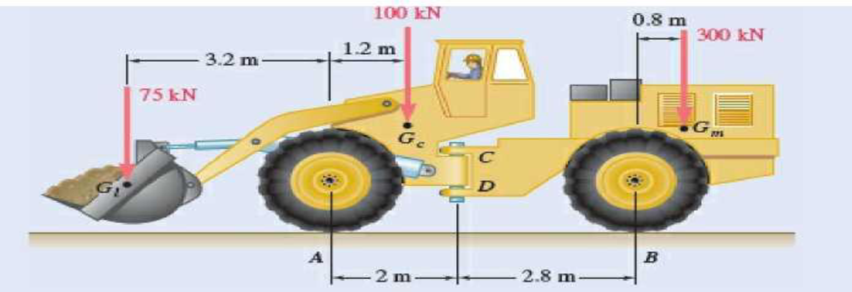
Fig. P6.97
Expert Solution & Answer
Want to see the full answer?
Check out a sample textbook solution
Students have asked these similar questions
Required information
Water initially at 200 kPa and 300°C is contained in a piston-cylinder device fitted with stops. The water is allowed to cool
at constant pressure until it exists as a saturated vapor and the piston rests on the stops. Then the water continues to cool
until the pressure is 100 kPa.
NOTE: This is a multi-part question. Once an answer is submitted, you will be unable to return to this part.
Water
200 kPa
300°C
On the T-V diagram, sketch, with respect to the saturation lines, the process curves passing through the initial, intermediate, and final states of the water. Label the
T, P, and V values for end states on the process curves.
Please upload your response/solution by using the controls provided below.
A piston-cylinder device contains 0.87 kg of refrigerant-134a at -10°C. The piston that is free to move has a mass of 12 kg
and a diameter of 25 cm. The local atmospheric pressure is 88 kPa. Now, heat is transferred to refrigerant-134a until the
temperature is 15°C. Use data from the tables.
R-134a
-10°C
Determine the change in the volume of the cylinder of the refrigerant-134a if the specific volume and enthalpy of R-134a at the initial
state of 90.4 kPa and -10°C and at the final state of 90.4 kPa and 15°C are as follows:
= 0.2418 m³/kg, h₁ = 247.77 kJ/kg
3
v2 = 0.2670 m³/kg, and h₂ = 268.18 kJ/kg
The change in the volume of the cylinder is
m
A piston-cylinder device contains 0.87 kg of refrigerant-134a at -10°C. The piston that is free to move has a mass of 12 kg
and a diameter of 25 cm. The local atmospheric pressure is 88 kPa. Now, heat is transferred to refrigerant-134a until the
temperature is 15°C. Use data from the tables.
R-134a
-10°C
Determine the final pressure of the refrigerant-134a.
The final pressure is
kPa.
Chapter 6 Solutions
Vector Mechanics for Engineers: Statics, 11th Edition
Ch. 6.1 - 6.1 through 6.8 Using the method of joints,...Ch. 6.1 - Prob. 6.2PCh. 6.1 - Prob. 6.3PCh. 6.1 - 6.1 through 6.8 Using the method of joints,...Ch. 6.1 - 6.1 through 6.8 Using the method of joints,...Ch. 6.1 - Using the method of joints, determine the force in...Ch. 6.1 - 6.1 through 6.8 Using the method of joints,...Ch. 6.1 - Prob. 6.8PCh. 6.1 - 6.9 and 6.10 Determine the force in each member of...Ch. 6.1 - 6.9 and 6.10 Determine the force in each member of...
Ch. 6.1 - Determine the force in each member of the Gambrel...Ch. 6.1 - Determine the force in each member of the Howe...Ch. 6.1 - Using the method of joints, determine the force in...Ch. 6.1 - 6.14 Determine the force in each member of the...Ch. 6.1 - Determine the force in each member of the Warren...Ch. 6.1 - Solve Problem 6.15 assuming that the load applied...Ch. 6.1 - Determine the force in each member of the Pratt...Ch. 6.1 - The truss shown is one of several supporting an...Ch. 6.1 - Determine the force in each member of the Pratt...Ch. 6.1 - Solve Problem 6.19 assuming that the load applied...Ch. 6.1 - Determine the force in each of the members located...Ch. 6.1 - Determine the force in member DE and in each of...Ch. 6.1 - Determine the force in each of the members located...Ch. 6.1 - The portion of truss shown represents the upper...Ch. 6.1 - For the tower and loading of Prob. 6.24 and...Ch. 6.1 - Solve Problem 6.24 assuming that the cables...Ch. 6.1 - Determine the force in each member of the truss...Ch. 6.1 - Determine the force in each member of the truss...Ch. 6.1 - Prob. 6.29PCh. 6.1 - 6.30 Determine whether the trusses of Probs....Ch. 6.1 - 6.31 For the given loading. determine the...Ch. 6.1 - For the given loading, determine the zero-force...Ch. 6.1 - For the given loading, determine the zero-force...Ch. 6.1 - Determine the zero-force members in the truss of...Ch. 6.1 - The truss shown consists of six members and is...Ch. 6.1 - The truss shown consists of six members and is...Ch. 6.1 - The truss shown consists of six members and is...Ch. 6.1 - Prob. 6.38PCh. 6.1 - The truss shown consists of nine members and is...Ch. 6.1 - Solve Prob. 6.39 for P = 0 and Q = (900 N)k. 6.39...Ch. 6.1 - The truss shown consists of 18 members and is...Ch. 6.1 - The truss shown consists of 18 members and is...Ch. 6.2 - 6 .43 A Mansard roof truss is loaded as shown....Ch. 6.2 - Prob. 6.44PCh. 6.2 - Determine the force in members BD and CD of the...Ch. 6.2 - Determine the force in members DF and DG of the...Ch. 6.2 - 6.47 Determine the force in members CD and DF of...Ch. 6.2 - Prob. 6.48PCh. 6.2 - Determine the force in members CD and DF of the...Ch. 6.2 - Determine the force in members CE and EF of the...Ch. 6.2 - Determine the force in members DE and DF of the...Ch. 6.2 - Determine the force in members EG and EF of the...Ch. 6.2 - Determine the force in members DF and DE of the...Ch. 6.2 - Determine the force in members CD and CE of the...Ch. 6.2 - Prob. 6.55PCh. 6.2 - 6.56 A monosloped roof truss is loaded as shown....Ch. 6.2 - A Howe scissors roof truss is loaded as shown....Ch. 6.2 - A Howe scissors roof truss is loaded as shown....Ch. 6.2 - Determine the force in members AD, CD, and CE of...Ch. 6.2 - Determine the force in members DG, FG, and FH of...Ch. 6.2 - 6.61 Determine the force in members DC and FI of...Ch. 6.2 - Prob. 6.62PCh. 6.2 - Prob. 6.63PCh. 6.2 - Prob. 6.64PCh. 6.2 - The diagonal members in the center panels of the...Ch. 6.2 - The diagonal members in the center panels of the...Ch. 6.2 - The diagonal members in the center panels of the...Ch. 6.2 - Solve Prob. 6.67 assuming that the 9-kip load has...Ch. 6.2 - Classify each of the structures shown as...Ch. 6.2 - Classify each of the structures shown as...Ch. 6.2 - 6.70 through 6.74 classify as determinate or...Ch. 6.2 - 6.70 through 6.74 classify as determinate or...Ch. 6.2 - 6.70 through 6.74 classify as determinate or...Ch. 6.2 - 6.70 through 6.74 classify as determinate or...Ch. 6.3 - For the frame and loading shown, draw the...Ch. 6.3 - For the frame and loading shown, draw the...Ch. 6.3 - Draw the free-body diagram(s) needed to determine...Ch. 6.3 - Knowing that the pulley has a radius of 0.5 m,...Ch. 6.3 - 6.75 and 6.76 Determine the force in member BD and...Ch. 6.3 - 6.75 and 6.76 Determine the force in member BD and...Ch. 6.3 - For the frame and loading shown, determine the...Ch. 6.3 - Determine the components of all forces acting on...Ch. 6.3 - Prob. 6.79PCh. 6.3 - Prob. 6.80PCh. 6.3 - Determine the components of all forces acting on...Ch. 6.3 - Determine the components of all forces acting on...Ch. 6.3 - Determine the components of the reactions at A and...Ch. 6.3 - Determine the components of the reactions at D and...Ch. 6.3 - Determine the components of the reactions at A and...Ch. 6.3 - Determine the components of the reactions at A and...Ch. 6.3 - Prob. 6.87PCh. 6.3 - The 48-lb load can be moved along the line of...Ch. 6.3 - The 48-lb load is removed and a 288-lb in....Ch. 6.3 - (a) Show that, when a frame supports a pulley at...Ch. 6.3 - Knowing that each pulley has a radius of 250 mm,...Ch. 6.3 - Knowing that the pulley has a radius of 75 mm,...Ch. 6.3 - 6.93 A 3-ft-diameter pipe is supported every 16 ft...Ch. 6.3 - Prob. 6.94PCh. 6.3 - A trailer weighing 2400 lb is attached to a...Ch. 6.3 - In order to obtain a better weight distribution...Ch. 6.3 - The cab and motor units of the front-end loader...Ch. 6.3 - Solve Problem 6.97 assuming that the 75-kN load...Ch. 6.3 - Knowing that P = 90 lb and Q = 60 lb, determine...Ch. 6.3 - Knowing that P = 90 lb and Q = 60 lb, determine...Ch. 6.3 - For the frame and loading shown, determine the...Ch. 6.3 - For the frame and loading shown, determine the...Ch. 6.3 - 6.103 For the frame and loading shown, determine...Ch. 6.3 - Prob. 6.104PCh. 6.3 - For the frame and loading shown, determine the...Ch. 6.3 - Solve Prob. 6.105 assuming that the 6-kN load has...Ch. 6.3 - The axis of the three-hinge arch ABC is a parabola...Ch. 6.3 - The axis of the three-hinge arch ABC is a parabola...Ch. 6.3 - 6.109 and 6.110 Neglecting the effect of friction...Ch. 6.3 - and 6.110 Neglecting the effect of friction at the...Ch. 6.3 - 6.111, 6.112, and 6.113 Members ABC and CDE are...Ch. 6.3 - 6.111, 6.112, and 6.113 Members ABC and CDE are...Ch. 6.3 - 6.111, 6.112, and 6.113 Members ABC and CDE are...Ch. 6.3 - Prob. 6.114PCh. 6.3 - Solve Prob. 6.112 assuming that the force P is...Ch. 6.3 - Prob. 6.116PCh. 6.3 - Four beams, each with a length of 2a, are nailed...Ch. 6.3 - Four beams, each with a length of 3a, are held...Ch. 6.3 - 6.119 through 6.121 Each of the frames shown...Ch. 6.3 - 6.119 through 6.121 Each of the frames shown...Ch. 6.3 - 6.119 through 6.121 Each of the frames shown...Ch. 6.4 - An 84-lb force is applied to the toggle vise at C....Ch. 6.4 - For the system and loading shown, draw the...Ch. 6.4 - A small barrel weighing 60 lb is lifted by a pair...Ch. 6.4 - The position of member ABC is controlled by the...Ch. 6.4 - The shear shown is used to cut and trim...Ch. 6.4 - A 100-lb force directed vertically downward is...Ch. 6.4 - Prob. 6.124PCh. 6.4 - The control rod CE passes through a horizontal...Ch. 6.4 - Solve Prob. 6.125 when (a) = 0, (b) = 6. Fig....Ch. 6.4 - The press shown is used to emboss a small seal at...Ch. 6.4 - The press shown is used to emboss a small seal at...Ch. 6.4 - The pin at B is attached to member ABC and can...Ch. 6.4 - The pin at B is attached to member ABC and can...Ch. 6.4 - Arm ABC is connected by pins to a collar at B and...Ch. 6.4 - Arm ABC is connected by pins to a collar at B and...Ch. 6.4 - The Whitworth mechanism shown is used to produce a...Ch. 6.4 - Solve Prob. 6.133 when (a) = 60, (b) = 90. Fig....Ch. 6.4 - Prob. 6.135PCh. 6.4 - 6.135 and 6.136 Two rods are connected by a...Ch. 6.4 - 6.137 and 6.138 Rod CD is attached to the collar D...Ch. 6.4 - 6.137 and 6.138 Rod CD is attached to the collar D...Ch. 6.4 - Two hydraulic cylinders control the position of...Ch. 6.4 - Two hydraulic cylinders control the position of...Ch. 6.4 - Prob. 6.141PCh. 6.4 - Prob. 6.142PCh. 6.4 - 6.143 The tongs shown are used to apply a total...Ch. 6.4 - Prob. 6.144PCh. 6.4 - The pliers shown are used to grip a...Ch. 6.4 - Prob. 6.146PCh. 6.4 - In using the bolt cutter shown, a worker applies...Ch. 6.4 - Prob. 6.148PCh. 6.4 - and 6.150 Determine the force P that must be...Ch. 6.4 - and 6.150 Determine the force P that must be...Ch. 6.4 - Because the brace shown must remain in position...Ch. 6.4 - The specialized plumbing wrench shown is used in...Ch. 6.4 - Prob. 6.153PCh. 6.4 - Prob. 6.154PCh. 6.4 - The telescoping arm ABC is used to provide an...Ch. 6.4 - The telescoping arm ABC of Prob. 6.155 can be...Ch. 6.4 - The motion of the backhoe bucket shown is...Ch. 6.4 - Solve Prob. 6.157 assuming that the 2-kip force P...Ch. 6.4 - Prob. 6.159PCh. 6.4 - In the planetary gear system shown, the radius of...Ch. 6.4 - Two shafts AC and CF, which lie in the vertical xy...Ch. 6.4 - Two shafts AC and CF, which lie in the vertical xy...Ch. 6.4 - The large mechanical tongs shown are used to grab...Ch. 6 - Using the method of joints, determine the force in...Ch. 6 - Using the method of joints, determine the force in...Ch. 6 - A stadium roof truss is loaded as shown. Determine...Ch. 6 - A stadium roof truss is loaded as shown. Determine...Ch. 6 - Determine the components of all forces acting on...Ch. 6 - Determine the components of the reactions at A and...Ch. 6 - Knowing that the pulley has a radius of 50 mm,...Ch. 6 - For the frame and loading shown, determine the...Ch. 6 - For the frame and loading shown, determine the...Ch. 6 - Water pressure in the supply system exerts a...Ch. 6 - A couple M with a magnitude of 1.5 kNm is applied...Ch. 6 - The compound-lever pruning shears shown can be...
Knowledge Booster


Learn more about
Need a deep-dive on the concept behind this application? Look no further. Learn more about this topic, mechanical-engineering and related others by exploring similar questions and additional content below.Similar questions
- The hydraulic cylinder BC exerts on member AB a force P directed along line BC. The force P must have a 560-N component perpendicular to member AB. A M 45° 30° C Determine the force component along line AB. The force component along line AB is N.arrow_forward! Required information A telephone cable is clamped at A to the pole AB. The tension in the left-hand portion of the cable is given to be T₁ = 815 lb. A 15° 25° B T₂ Using trigonometry, determine the required tension T₂ in the right-hand portion if the resultant R of the forces exerted by the cable at A is to be vertical. The required tension is lb.arrow_forwardWhat are examples of at least three (3) applications of tolerance fitting analysis.arrow_forward
- The primary material used in the production of glass products is silica sand. True or Falsearrow_forwardWhich one of the following is the most common polymer type in fiber-reinforced polymer composites? thermosets thermoplastics elastomers none of the abovearrow_forwardA pattern for a product is larger than the actual finished part. True or Falsearrow_forward
- Two forces are applied as shown to a hook support. The magnitude of P is 38 N. 50 N 25° DG a 터 Using trigonometry, determine the required angle a such that the resultant R of the two forces applied to the support will be horizontal. The value of a isarrow_forwardNo chatgpt pls will upvotearrow_forward101 the three shafts if the diameter ratio is 2 (D/d = 2)? Ans. na, tension = 1.21, na, bending = 1.19, na, torsion = 1.17. 6.32 A material with a yield strength of S₁ = 350 MPa is subjected to the stress state shown in Sketch c. What is the factor of safety based on the maximum shear stress and distortion energy theories? Ans. For MSST, n, = 11.67. 50 MPa 85 MPa 20 MPa 70 MPa Sketch c, for Problems 6.32 and 6.33arrow_forward
arrow_back_ios
SEE MORE QUESTIONS
arrow_forward_ios
Recommended textbooks for you
 Elements Of ElectromagneticsMechanical EngineeringISBN:9780190698614Author:Sadiku, Matthew N. O.Publisher:Oxford University Press
 Mechanics of Materials (10th Edition)Mechanical EngineeringISBN:9780134319650Author:Russell C. HibbelerPublisher:PEARSON
 Thermodynamics: An Engineering ApproachMechanical EngineeringISBN:9781259822674Author:Yunus A. Cengel Dr., Michael A. BolesPublisher:McGraw-Hill Education
 Control Systems EngineeringMechanical EngineeringISBN:9781118170519Author:Norman S. NisePublisher:WILEY
 Mechanics of Materials (MindTap Course List)Mechanical EngineeringISBN:9781337093347Author:Barry J. Goodno, James M. GerePublisher:Cengage Learning
 Engineering Mechanics: StaticsMechanical EngineeringISBN:9781118807330Author:James L. Meriam, L. G. Kraige, J. N. BoltonPublisher:WILEY
Elements Of Electromagnetics
Mechanical Engineering
ISBN:9780190698614
Author:Sadiku, Matthew N. O.
Publisher:Oxford University Press
Mechanics of Materials (10th Edition)
Mechanical Engineering
ISBN:9780134319650
Author:Russell C. Hibbeler
Publisher:PEARSON
Thermodynamics: An Engineering Approach
Mechanical Engineering
ISBN:9781259822674
Author:Yunus A. Cengel Dr., Michael A. Boles
Publisher:McGraw-Hill Education
Control Systems Engineering
Mechanical Engineering
ISBN:9781118170519
Author:Norman S. Nise
Publisher:WILEY
Mechanics of Materials (MindTap Course List)
Mechanical Engineering
ISBN:9781337093347
Author:Barry J. Goodno, James M. Gere
Publisher:Cengage Learning
Engineering Mechanics: Statics
Mechanical Engineering
ISBN:9781118807330
Author:James L. Meriam, L. G. Kraige, J. N. Bolton
Publisher:WILEY
Dynamics - Lesson 1: Introduction and Constant Acceleration Equations; Author: Jeff Hanson;https://www.youtube.com/watch?v=7aMiZ3b0Ieg;License: Standard YouTube License, CC-BY