
Vector Mechanics for Engineers: Statics, 11th Edition
11th Edition
ISBN: 9780077687304
Author: Ferdinand P. Beer, E. Russell Johnston Jr., David Mazurek
Publisher: McGraw-Hill Education
expand_more
expand_more
format_list_bulleted
Videos
Textbook Question
Chapter 6.4, Problem 6.132P
Arm ABC is connected by pins to a collar at B and to crank CD at C. Neglecting the effect of friction, determine the couple M required to hold the system in equilibrium when θ = 90°.
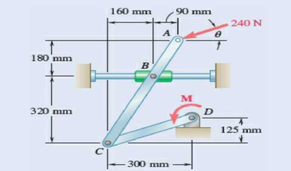
Fig. P6.131 and P6.132
Expert Solution & Answer
Want to see the full answer?
Check out a sample textbook solution
Students have asked these similar questions
This problem illustrates that the factor of safety for a machine element depends on the particular point selected for
analysis. Here you are to compute factors of safety, based upon the distortion-energy theory, for stress elements at A and
B of the member shown in the figure. This bar is made of AISI 1006 cold-drawn steel and is loaded by the forces
F = 1.100 kN, P = 8.00 kN, and T = 50.00 N·m. Given: Sy = 280 MPa.
B
-100 mm-
15-mm D.
a) What is the value of the axial stress at point A?
b)What is the value of the shear stress at point A?
c)Determine the value of the Von Mises stress at
point A.
P
F
The three steel wires, each of cross-sectional area 0.05 in2, support the weight W. Theirunstressed lengths are 74.98 ft, 74.99 ft, and 75.00 ft. Use E = 29 x 106 psi.1. Find the stress (psi) in the longest wire if W = 1500 lb.2. Determine the stress in the shortest wire if W = 500 lb
ANSWERS: 6130 psi; 6930 psi
1: The concrete column is reinforced using four steel reinforcing rods, each having a diameter of 18 mm. Determine the stress in the concrete and the steel if the column is subjected to an axial load of 800 kN. Est = 200 GPa, Ec = 25 GPa. Complete fbd.
Chapter 6 Solutions
Vector Mechanics for Engineers: Statics, 11th Edition
Ch. 6.1 - 6.1 through 6.8 Using the method of joints,...Ch. 6.1 - Prob. 6.2PCh. 6.1 - Prob. 6.3PCh. 6.1 - 6.1 through 6.8 Using the method of joints,...Ch. 6.1 - 6.1 through 6.8 Using the method of joints,...Ch. 6.1 - Using the method of joints, determine the force in...Ch. 6.1 - 6.1 through 6.8 Using the method of joints,...Ch. 6.1 - Prob. 6.8PCh. 6.1 - 6.9 and 6.10 Determine the force in each member of...Ch. 6.1 - 6.9 and 6.10 Determine the force in each member of...
Ch. 6.1 - Determine the force in each member of the Gambrel...Ch. 6.1 - Determine the force in each member of the Howe...Ch. 6.1 - Using the method of joints, determine the force in...Ch. 6.1 - 6.14 Determine the force in each member of the...Ch. 6.1 - Determine the force in each member of the Warren...Ch. 6.1 - Solve Problem 6.15 assuming that the load applied...Ch. 6.1 - Determine the force in each member of the Pratt...Ch. 6.1 - The truss shown is one of several supporting an...Ch. 6.1 - Determine the force in each member of the Pratt...Ch. 6.1 - Solve Problem 6.19 assuming that the load applied...Ch. 6.1 - Determine the force in each of the members located...Ch. 6.1 - Determine the force in member DE and in each of...Ch. 6.1 - Determine the force in each of the members located...Ch. 6.1 - The portion of truss shown represents the upper...Ch. 6.1 - For the tower and loading of Prob. 6.24 and...Ch. 6.1 - Solve Problem 6.24 assuming that the cables...Ch. 6.1 - Determine the force in each member of the truss...Ch. 6.1 - Determine the force in each member of the truss...Ch. 6.1 - Prob. 6.29PCh. 6.1 - 6.30 Determine whether the trusses of Probs....Ch. 6.1 - 6.31 For the given loading. determine the...Ch. 6.1 - For the given loading, determine the zero-force...Ch. 6.1 - For the given loading, determine the zero-force...Ch. 6.1 - Determine the zero-force members in the truss of...Ch. 6.1 - The truss shown consists of six members and is...Ch. 6.1 - The truss shown consists of six members and is...Ch. 6.1 - The truss shown consists of six members and is...Ch. 6.1 - Prob. 6.38PCh. 6.1 - The truss shown consists of nine members and is...Ch. 6.1 - Solve Prob. 6.39 for P = 0 and Q = (900 N)k. 6.39...Ch. 6.1 - The truss shown consists of 18 members and is...Ch. 6.1 - The truss shown consists of 18 members and is...Ch. 6.2 - 6 .43 A Mansard roof truss is loaded as shown....Ch. 6.2 - Prob. 6.44PCh. 6.2 - Determine the force in members BD and CD of the...Ch. 6.2 - Determine the force in members DF and DG of the...Ch. 6.2 - 6.47 Determine the force in members CD and DF of...Ch. 6.2 - Prob. 6.48PCh. 6.2 - Determine the force in members CD and DF of the...Ch. 6.2 - Determine the force in members CE and EF of the...Ch. 6.2 - Determine the force in members DE and DF of the...Ch. 6.2 - Determine the force in members EG and EF of the...Ch. 6.2 - Determine the force in members DF and DE of the...Ch. 6.2 - Determine the force in members CD and CE of the...Ch. 6.2 - Prob. 6.55PCh. 6.2 - 6.56 A monosloped roof truss is loaded as shown....Ch. 6.2 - A Howe scissors roof truss is loaded as shown....Ch. 6.2 - A Howe scissors roof truss is loaded as shown....Ch. 6.2 - Determine the force in members AD, CD, and CE of...Ch. 6.2 - Determine the force in members DG, FG, and FH of...Ch. 6.2 - 6.61 Determine the force in members DC and FI of...Ch. 6.2 - Prob. 6.62PCh. 6.2 - Prob. 6.63PCh. 6.2 - Prob. 6.64PCh. 6.2 - The diagonal members in the center panels of the...Ch. 6.2 - The diagonal members in the center panels of the...Ch. 6.2 - The diagonal members in the center panels of the...Ch. 6.2 - Solve Prob. 6.67 assuming that the 9-kip load has...Ch. 6.2 - Classify each of the structures shown as...Ch. 6.2 - Classify each of the structures shown as...Ch. 6.2 - 6.70 through 6.74 classify as determinate or...Ch. 6.2 - 6.70 through 6.74 classify as determinate or...Ch. 6.2 - 6.70 through 6.74 classify as determinate or...Ch. 6.2 - 6.70 through 6.74 classify as determinate or...Ch. 6.3 - For the frame and loading shown, draw the...Ch. 6.3 - For the frame and loading shown, draw the...Ch. 6.3 - Draw the free-body diagram(s) needed to determine...Ch. 6.3 - Knowing that the pulley has a radius of 0.5 m,...Ch. 6.3 - 6.75 and 6.76 Determine the force in member BD and...Ch. 6.3 - 6.75 and 6.76 Determine the force in member BD and...Ch. 6.3 - For the frame and loading shown, determine the...Ch. 6.3 - Determine the components of all forces acting on...Ch. 6.3 - Prob. 6.79PCh. 6.3 - Prob. 6.80PCh. 6.3 - Determine the components of all forces acting on...Ch. 6.3 - Determine the components of all forces acting on...Ch. 6.3 - Determine the components of the reactions at A and...Ch. 6.3 - Determine the components of the reactions at D and...Ch. 6.3 - Determine the components of the reactions at A and...Ch. 6.3 - Determine the components of the reactions at A and...Ch. 6.3 - Prob. 6.87PCh. 6.3 - The 48-lb load can be moved along the line of...Ch. 6.3 - The 48-lb load is removed and a 288-lb in....Ch. 6.3 - (a) Show that, when a frame supports a pulley at...Ch. 6.3 - Knowing that each pulley has a radius of 250 mm,...Ch. 6.3 - Knowing that the pulley has a radius of 75 mm,...Ch. 6.3 - 6.93 A 3-ft-diameter pipe is supported every 16 ft...Ch. 6.3 - Prob. 6.94PCh. 6.3 - A trailer weighing 2400 lb is attached to a...Ch. 6.3 - In order to obtain a better weight distribution...Ch. 6.3 - The cab and motor units of the front-end loader...Ch. 6.3 - Solve Problem 6.97 assuming that the 75-kN load...Ch. 6.3 - Knowing that P = 90 lb and Q = 60 lb, determine...Ch. 6.3 - Knowing that P = 90 lb and Q = 60 lb, determine...Ch. 6.3 - For the frame and loading shown, determine the...Ch. 6.3 - For the frame and loading shown, determine the...Ch. 6.3 - 6.103 For the frame and loading shown, determine...Ch. 6.3 - Prob. 6.104PCh. 6.3 - For the frame and loading shown, determine the...Ch. 6.3 - Solve Prob. 6.105 assuming that the 6-kN load has...Ch. 6.3 - The axis of the three-hinge arch ABC is a parabola...Ch. 6.3 - The axis of the three-hinge arch ABC is a parabola...Ch. 6.3 - 6.109 and 6.110 Neglecting the effect of friction...Ch. 6.3 - and 6.110 Neglecting the effect of friction at the...Ch. 6.3 - 6.111, 6.112, and 6.113 Members ABC and CDE are...Ch. 6.3 - 6.111, 6.112, and 6.113 Members ABC and CDE are...Ch. 6.3 - 6.111, 6.112, and 6.113 Members ABC and CDE are...Ch. 6.3 - Prob. 6.114PCh. 6.3 - Solve Prob. 6.112 assuming that the force P is...Ch. 6.3 - Prob. 6.116PCh. 6.3 - Four beams, each with a length of 2a, are nailed...Ch. 6.3 - Four beams, each with a length of 3a, are held...Ch. 6.3 - 6.119 through 6.121 Each of the frames shown...Ch. 6.3 - 6.119 through 6.121 Each of the frames shown...Ch. 6.3 - 6.119 through 6.121 Each of the frames shown...Ch. 6.4 - An 84-lb force is applied to the toggle vise at C....Ch. 6.4 - For the system and loading shown, draw the...Ch. 6.4 - A small barrel weighing 60 lb is lifted by a pair...Ch. 6.4 - The position of member ABC is controlled by the...Ch. 6.4 - The shear shown is used to cut and trim...Ch. 6.4 - A 100-lb force directed vertically downward is...Ch. 6.4 - Prob. 6.124PCh. 6.4 - The control rod CE passes through a horizontal...Ch. 6.4 - Solve Prob. 6.125 when (a) = 0, (b) = 6. Fig....Ch. 6.4 - The press shown is used to emboss a small seal at...Ch. 6.4 - The press shown is used to emboss a small seal at...Ch. 6.4 - The pin at B is attached to member ABC and can...Ch. 6.4 - The pin at B is attached to member ABC and can...Ch. 6.4 - Arm ABC is connected by pins to a collar at B and...Ch. 6.4 - Arm ABC is connected by pins to a collar at B and...Ch. 6.4 - The Whitworth mechanism shown is used to produce a...Ch. 6.4 - Solve Prob. 6.133 when (a) = 60, (b) = 90. Fig....Ch. 6.4 - Prob. 6.135PCh. 6.4 - 6.135 and 6.136 Two rods are connected by a...Ch. 6.4 - 6.137 and 6.138 Rod CD is attached to the collar D...Ch. 6.4 - 6.137 and 6.138 Rod CD is attached to the collar D...Ch. 6.4 - Two hydraulic cylinders control the position of...Ch. 6.4 - Two hydraulic cylinders control the position of...Ch. 6.4 - Prob. 6.141PCh. 6.4 - Prob. 6.142PCh. 6.4 - 6.143 The tongs shown are used to apply a total...Ch. 6.4 - Prob. 6.144PCh. 6.4 - The pliers shown are used to grip a...Ch. 6.4 - Prob. 6.146PCh. 6.4 - In using the bolt cutter shown, a worker applies...Ch. 6.4 - Prob. 6.148PCh. 6.4 - and 6.150 Determine the force P that must be...Ch. 6.4 - and 6.150 Determine the force P that must be...Ch. 6.4 - Because the brace shown must remain in position...Ch. 6.4 - The specialized plumbing wrench shown is used in...Ch. 6.4 - Prob. 6.153PCh. 6.4 - Prob. 6.154PCh. 6.4 - The telescoping arm ABC is used to provide an...Ch. 6.4 - The telescoping arm ABC of Prob. 6.155 can be...Ch. 6.4 - The motion of the backhoe bucket shown is...Ch. 6.4 - Solve Prob. 6.157 assuming that the 2-kip force P...Ch. 6.4 - Prob. 6.159PCh. 6.4 - In the planetary gear system shown, the radius of...Ch. 6.4 - Two shafts AC and CF, which lie in the vertical xy...Ch. 6.4 - Two shafts AC and CF, which lie in the vertical xy...Ch. 6.4 - The large mechanical tongs shown are used to grab...Ch. 6 - Using the method of joints, determine the force in...Ch. 6 - Using the method of joints, determine the force in...Ch. 6 - A stadium roof truss is loaded as shown. Determine...Ch. 6 - A stadium roof truss is loaded as shown. Determine...Ch. 6 - Determine the components of all forces acting on...Ch. 6 - Determine the components of the reactions at A and...Ch. 6 - Knowing that the pulley has a radius of 50 mm,...Ch. 6 - For the frame and loading shown, determine the...Ch. 6 - For the frame and loading shown, determine the...Ch. 6 - Water pressure in the supply system exerts a...Ch. 6 - A couple M with a magnitude of 1.5 kNm is applied...Ch. 6 - The compound-lever pruning shears shown can be...
Knowledge Booster


Learn more about
Need a deep-dive on the concept behind this application? Look no further. Learn more about this topic, mechanical-engineering and related others by exploring similar questions and additional content below.Similar questions
- 5: As shown, two aluminum rods AB and BC, hinged to rigid supports, arepinned together at B to carry a vertical load P = 6000 lb. If each rod has a crosssectional area of 0.60 in2 and E = 10 x 106 psi. Use α = θ = 30⁰. Calculate the change in length (in) of rod AB and indicate if it elongates orshortens. Calculate the vertical displacement of B (in) and horizontal displacement of B (in). Complete fbd.arrow_forward2: The rigid bar supports the uniform distributedload of 6 kip/ft. Determine the force in each cable if each cable has a cross-sectional area of 0.05 in^2 , and E = 31(10)^3 ksi.arrow_forwardIn (Figure 1), take m₁ = 4 kg and mB = 4.6 kg. Determine the z component of the angular momentum Ho of particle A about point O. Determine the z component of the angular momentum Ho of particle B about point O. Suppose that 5 m 8 m/s 4 m 1.5 m 4 m B MB 1 m 2 m 5 30° 6 m/s MAarrow_forward
- The two disks A and B have a mass of 4 kg and 6 kg, respectively. They collide with the initial velocities shown. The coefficient of restitution is e = 0.75. Suppose that (VA)1 = 6 m/s, (VB)₁ = 7 m/s. (Figure 1) Determine the magnitude of the velocity of A just after impact. Determine the angle between the x axis and the velocity of A just after impact, measured clockwise from the negative x axis. Determine the magnitude of the velocity of B just after impact. Determine the angle between the x axis and the velocity of B just after impact, measured clockwise from the positive x axis. (VB)1 B (VA)1 60° Line of impactarrow_forwardA hot plane surface is maintained at 100°C, and it is exposed to air at 25°C.The combined heat transfer coefficient between the surface and the air is 25W/m²·K. (same as above). In this task, you are asked to design fins to cool asurface by attaching 3 cm-long, 0.25 cm-diameter aluminum pin fins (thermalconductivity, k = 237 W/m·K) with a center-to-center distance of 0.6 cm. (Tip:do not correct the length). Determine the rate of heat transfer from thefinned structure to the air for a 1 m x 1 m section of the plate.arrow_forwardHeat is generated uniformly in a 4 cm-diameter, 16-cm long solid bar (k=2.4 W/m-K). The temperaturesat the center and at the surface of the bar are measured to be 210 oC and 45 oC, respectively. Calculatethe rate of heat generation within the bar. Solve the relevant energy balance equation and the boundaryconditions to calculate the rate of heat generation within the bar. (6 pts)arrow_forward
- A hot plane surface is maintained at 100°C, and it is exposed to air at 25°C. The combined heat transfercoefficient between the surface and the air is 25 W/m²·K. You are tasked with designing an insulatingmaterial to cover the surface in order to reduce the heat transfer rate by 90%, meaning only 10% of theheat transfer would occur compared to the situation without insulation. The available insulating materialhas a thermal conductivity of 0.093 W/m·K. Assuming that the heat transfer coefficient and the surface/airtemperatures remain constant, calculate the required thickness of the insulating material in centimeters.arrow_forwardThe euler parameter in the image describes the orientation of N in the reference frame of U. How do I find the euler parameters that describe the orientation of U in the reference frame of N from the given information in the image.arrow_forwardFpull Ө A person, weighing 155 lb, is being lifted by a rope thrown. over a tree branch as shown (drawing not to scale). If the static coefficient of friction between the rope and the tree branch is us = 0.67, and the 0 = 45°. Determine the pulling force required to start lifting the person and the pulling force required to keep the person from falling? Pulling force to lift the person: Pulling force to keep the person from falling: lb lbarrow_forward
- The car weighs 1630 lbs and drives up the hill at a constant speed. Assuming the static friction coefficient between the wheels and the road is μs = 0.64, determine the steepest angle that the car can climb without slipping if it is.... a.) rear wheel drive b.) front wheel drive c.) four wheel drive a C CC ①⑧ BY NC Dr. Jacob Moore Values for dimensions on the figure are given in the following table. Note the figure may not be to scale. Variable Value a 8.75 ft b 3.325 ft C 1.66 ft a.) The steepest angle for rear wheel drive is 0 max degrees. b.) The steepest angle for front wheel drive is Omax degrees. c.) The steepest angle for four wheel drive is Omax degrees. = = =arrow_forwardFor the structure below, each member of the truss will safely support a tensile force of 3 kN and a compressive force of 1 kN. Determine the largest mass m that can be safely suspended. Hint: First work through this algebraically to find the forces in each member terms of the mass "m" to determine the largest stress member. 1 m t 1 m 1 m 1m + 1m E B 1977 marrow_forwardBlock A has a mass of 34 kg and block B has a mass of 41 kg. The two blocks are stacked on the ramp with an incline of Ꮎ 0 = 15.4°. Determine the largest horizontal force F that can be applied to block B without either block moving for each of the following two cases: a.) The friction coefficient for the contact between blocks A and B is μs1 0.56 and the friction coefficient for the = contact between block A and the ramp is μs2 = 0.34. b.) The friction coefficient for the contact between blocks A and B is 1 = 0.56 and the friction coefficient for the contact between block A and the ramp is μs2 = 0.17. Ꮎ F B A Part a) The limiting slip condition occurs at Select an answer CC BY NC SA 2016 Eric Davishahl The maximum force before either block A or B slips is N Part b) The limiting slip condition occurs at Select an answer The maximum force before either block A or B slips is Narrow_forward
arrow_back_ios
SEE MORE QUESTIONS
arrow_forward_ios
Recommended textbooks for you
 Elements Of ElectromagneticsMechanical EngineeringISBN:9780190698614Author:Sadiku, Matthew N. O.Publisher:Oxford University Press
 Mechanics of Materials (10th Edition)Mechanical EngineeringISBN:9780134319650Author:Russell C. HibbelerPublisher:PEARSON
 Thermodynamics: An Engineering ApproachMechanical EngineeringISBN:9781259822674Author:Yunus A. Cengel Dr., Michael A. BolesPublisher:McGraw-Hill Education
 Control Systems EngineeringMechanical EngineeringISBN:9781118170519Author:Norman S. NisePublisher:WILEY
 Mechanics of Materials (MindTap Course List)Mechanical EngineeringISBN:9781337093347Author:Barry J. Goodno, James M. GerePublisher:Cengage Learning
 Engineering Mechanics: StaticsMechanical EngineeringISBN:9781118807330Author:James L. Meriam, L. G. Kraige, J. N. BoltonPublisher:WILEY
Elements Of Electromagnetics
Mechanical Engineering
ISBN:9780190698614
Author:Sadiku, Matthew N. O.
Publisher:Oxford University Press
Mechanics of Materials (10th Edition)
Mechanical Engineering
ISBN:9780134319650
Author:Russell C. Hibbeler
Publisher:PEARSON
Thermodynamics: An Engineering Approach
Mechanical Engineering
ISBN:9781259822674
Author:Yunus A. Cengel Dr., Michael A. Boles
Publisher:McGraw-Hill Education
Control Systems Engineering
Mechanical Engineering
ISBN:9781118170519
Author:Norman S. Nise
Publisher:WILEY
Mechanics of Materials (MindTap Course List)
Mechanical Engineering
ISBN:9781337093347
Author:Barry J. Goodno, James M. Gere
Publisher:Cengage Learning
Engineering Mechanics: Statics
Mechanical Engineering
ISBN:9781118807330
Author:James L. Meriam, L. G. Kraige, J. N. Bolton
Publisher:WILEY
Material Science, Phase Diagrams, Part 1; Author: Welt der Werkstoffe;https://www.youtube.com/watch?v=G83ZaoB3XCc;License: Standard Youtube License