
Loose Leaf for Engineering Circuit Analysis Format: Loose-leaf
9th Edition
ISBN: 9781259989452
Author: Hayt
Publisher: Mcgraw Hill Publishers
expand_more
expand_more
format_list_bulleted
Concept explainers
Videos
Textbook Question
Chapter 5.3, Problem 5P
Using repeated source transformations, determine the Norton equivalent of the highlighted network in the circuit of Fig. 5.26.
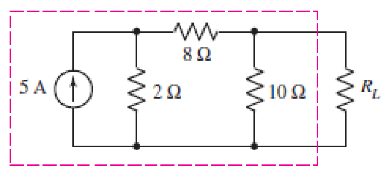
■ FIGURE 5.26
Expert Solution & Answer

Trending nowThis is a popular solution!

Students have asked these similar questions
"Can you explain the method of choosing the
direction?"
Question- A plane wave in a non-magnetic medium
=
Нр 1 has an electric field-
E = 50 sin(10®t +2)ây
V
m
The standard equation of the electric field is- How can
E = Eosin(t + Bây
V
m
✓ explan how
(C. i)- The direction of the propagation is-âk = - âz
the direction
|
Express this graph/signal as a sum of singularity functions. Please give a proper solution.
2) A 208 V, four-pole, 60 Hz, Y-connected, wound-rotor induction motor has a rated power of 30 HP. The components of its equivalent circuit are R1 = 0.100
R2 = 0.070
XM = 10.0
X1 = 0.210
X2 = 0.210
Pmec = 500 W
Psup ~ 0
Pcore = 400 W
For a slip of 0.05, find:
a) The line current
b) The stator copper losses PcE
c) The air gap power PEF
d) The power converted from mechanical to electrical form Pconv
e) The induced torque _ind
f) load torque _load
g) The total efficiency of the machine
h) The speed of the motor in revolutions per minute and in radians per second
Chapter 5 Solutions
Loose Leaf for Engineering Circuit Analysis Format: Loose-leaf
Ch. 5.1 - For the circuit of Fig. 5.4, use superposition to...Ch. 5.2 - For the circuit of Fig. 5.7, use superposition to...Ch. 5.2 - For the circuit of Fig. 5.18, compute the current...Ch. 5.2 - For the circuit of Fig. 5.20, compute the voltage...Ch. 5.3 - Using repeated source transformations, determine...Ch. 5.3 - Use Thvenins theorem to find the current through...Ch. 5.3 - Determine the Thvenin and Norton equivalents of...Ch. 5.3 - Find the Thvenin equivalent for the network of...Ch. 5.3 - Find the Thvenin equivalent for the network of...Ch. 5.4 - Consider the circuit of Fig. 5.43. FIGURE 5.43...
Ch. 5.5 - Prob. 11PCh. 5 - Linear systems are so easy to work with that...Ch. 5 - Prob. 2ECh. 5 - Prob. 3ECh. 5 - (a) Employ superposition to determine the current...Ch. 5 - (a) Using superposition to consider each source...Ch. 5 - (a) Determine the individual contributions of each...Ch. 5 - (a) Determine the individual contributions of each...Ch. 5 - After studying the circuit of Fig. 5.53, change...Ch. 5 - Consider the three circuits shown in Fig. 5.54....Ch. 5 - (a) Using superposition, determine the voltage...Ch. 5 - Employ superposition principles to obtain a value...Ch. 5 - (a) Employ superposition to determine the...Ch. 5 - Perform an appropriate source transformation on...Ch. 5 - (a) For the circuit of Fig. 5.59, plot iL versus...Ch. 5 - Determine the current labeled I in the circuit of...Ch. 5 - Verify that the power absorbed by the 7 resistor...Ch. 5 - (a) Determine the current labeled i in the circuit...Ch. 5 - (a) Using repeated source transformations, reduce...Ch. 5 - Prob. 19ECh. 5 - (a) Making use of repeated source transformations,...Ch. 5 - Prob. 21ECh. 5 - (a) With the assistance of source transformations,...Ch. 5 - For the circuit in Fig. 5.67 transform all...Ch. 5 - Prob. 24ECh. 5 - (a) Referring to Fig. 5.69, determine the Thevenin...Ch. 5 - (a) With respect to the circuit depicted in Fig....Ch. 5 - (a) Obtain the Norton equivalent of the network...Ch. 5 - (a) Determine the Thevenin equivalent of the...Ch. 5 - Referring to the circuit of Fig. 5.71: (a)...Ch. 5 - Prob. 30ECh. 5 - (a) Employ Thvenins theorem to obtain a...Ch. 5 - Prob. 32ECh. 5 - Determine the Norton equivalent of the circuit...Ch. 5 - For the circuit of Fig. 5.75: (a) Employ Nortons...Ch. 5 - (a) Obtain a value for the Thvenin equivalent...Ch. 5 - Prob. 36ECh. 5 - Obtain a value for the Thvenin equivalent...Ch. 5 - With regard to the network depicted in Fig. 5.79,...Ch. 5 - Determine the Thvenin and Norton equivalents of...Ch. 5 - Determine the Norton equivalent of the circuit...Ch. 5 - Prob. 41ECh. 5 - Determine the Thvenin and Norton equivalents of...Ch. 5 - Prob. 43ECh. 5 - Prob. 44ECh. 5 - Prob. 45ECh. 5 - (a) For the simple circuit of Fig. 5.87, find the...Ch. 5 - For the circuit drawn in Fig. 5.88, (a) determine...Ch. 5 - Study the circuit of Fig. 5.89. (a) Determine the...Ch. 5 - Prob. 49ECh. 5 - Prob. 50ECh. 5 - With reference to the circuit of Fig. 5.91, (a)...Ch. 5 - Prob. 52ECh. 5 - Select a value for RL in Fig. 5.93 such that it...Ch. 5 - Determine what value of resistance would absorb...Ch. 5 - Derive the equations required to convert from a...Ch. 5 - Convert the - (or "-") connected networks in Fig....Ch. 5 - Convert the Y-(or T-) connected networks in Fig....Ch. 5 - For the network of Fig. 5.97, select a value of R...Ch. 5 - For the network of Fig. 5.98, select a value of R...Ch. 5 - Prob. 60ECh. 5 - Calculate Rin as indicated in Fig.5.100. FIGURE...Ch. 5 - Employ Y conversion techniques as appropriate to...Ch. 5 - Prob. 63ECh. 5 - (a) Use appropriate techniques to obtain both the...Ch. 5 - (a) For the network in Fig. 5.104, replace the...Ch. 5 - Prob. 66ECh. 5 - Prob. 67ECh. 5 - A 2.57 load is connected between terminals a and...Ch. 5 - A load resistor is connected across the open...Ch. 5 - A backup is required for the circuit depicted in...Ch. 5 - (a) Explain in general terms how source...Ch. 5 - The load resistor in Fig. 5.108 can safely...Ch. 5 - Prob. 74ECh. 5 - As part of a security system, a very thin 100 ...Ch. 5 - With respect to the circuit in Fig. 5.90, (a)...
Knowledge Booster


Learn more about
Need a deep-dive on the concept behind this application? Look no further. Learn more about this topic, electrical-engineering and related others by exploring similar questions and additional content below.Similar questions
- 5. There are three sources that would affect the current flow in this circuit. Find the current through the 4k2 resistor that is caused solely by the 24V source (i.e., remove the 2mA and 12V sources using the correct methods). (20 points) 24 V + 9k, ww www 4kS 2mA 24ΚΩ www ++ 12V www 6k 24ΚΩarrow_forward"Can you explain the method of finding the direction?" the electric field in free space is given by ety E: 50 Cos [2π 10 t - Bz ] a) find the direction of the wave propagation b) Calculate W, B, A, S V/marrow_forwardAthle phase a.c. distributor AB has: The distance from A to B is 500 m. The distance from A to C is 800 m. The impedance of each section is (6+j 8) /km. A B C The voltage at the far end is maintained at 250 volt. Find: sending voltage, sending current, supply power factor and 80 A 60 A total voltage drop. 0.8 lag. P.f 0.6 lead. p.farrow_forward
- The transfer function H(s) = Y(s)/X(s) = Vo(s)/Vi(s) should be found from the circuit given that the initial conditions are equal to 0. Do not answer using AI Chatbots. PLEASEarrow_forwardA 10kW, 230V, long shunt compound DC generator has efficiency = 82%, armature resistance = 0.15 ohms, series field resistance = 0.1 ohm, shunt field resistance = 100 ohms. What are: armature current, armature voltage across the brushes, generated emf, total copper losses, and horsepower of prime mover?arrow_forwardThe capacitors in the circuit shown below have no energy stored in them and then switch “A” closes at time t=0. Find v(t) across the 6 uF capacitor for t≥0arrow_forward
- Consider the circuit Below: A) Find and show the Thevenin equivalent with respect to terminals a,b B) Find and show the Norton equivalent with respect to terminals a,b C)Find the value of Ro and the maximum power delivered across it when its adjusted such that the power across it is the maximum possible when connected in this fashionarrow_forwardConsider the Circuit Below: A)Find Vo if Vin is 0.2 volts and the positive and negative power supply voltages are +15v and -15v respectively. B)What is the Maximum of Vin that will not hit saturation for this circuit?arrow_forwardA shunt generator is rated at 125V, 25KW; armature resistance is 0.08 ohms, shunt field resistance is 25 ohms. What are: Armature voltage at rated load, armature power loss, shunt field power loss Total power generated in the armature?arrow_forward
- A 12KW, 240V 1500RPM shunt generator has an armature resistance of .02 ohm and a shunt field resistance of 160 ohms. The stray power losses are 900W. Assuming a constant shunt field current, what (1) the efficiency at rated load and (2) the efficiency of the generator at half-rated load?arrow_forward4. Consider the three circuits shown in Figure. Determine each output voltage for (i) V₁ = 3 V and (ii) VI = -5 V. 40 ΚΩ www ww 20 ΚΩ 10 ΚΩ (a) 01 να гля 40 ΚΩ www www 20 ΚΩ 10 ΚΩ ww 10 ΚΩ www (b) www 48 ΚΩ ww -0% 6 kQ 15 ΚΩ (c) оооarrow_forwardFind the mathematical expression for the points 1 and 2 for this pratical AM-DSB/SC modulatorarrow_forward
arrow_back_ios
SEE MORE QUESTIONS
arrow_forward_ios
Recommended textbooks for you
 Delmar's Standard Textbook Of ElectricityElectrical EngineeringISBN:9781337900348Author:Stephen L. HermanPublisher:Cengage Learning
Delmar's Standard Textbook Of Electricity
Electrical Engineering
ISBN:9781337900348
Author:Stephen L. Herman
Publisher:Cengage Learning
Latches and Flip-Flops 1 - The SR Latch; Author: Computer Science;https://www.youtube.com/watch?v=-aQH0ybMd3U;License: Standard Youtube License