
Concept explainers
Videos
(a)
Find the power dissipated by
(a)
Answer to Problem 41E
The power dissipated by
Explanation of Solution
Given Data:
The load resistance is
Formula used:
The expression for the power dissipated by load resistor is as follows.
Here,
Calculation:
The redrawn circuit diagram is given in Figure 1,
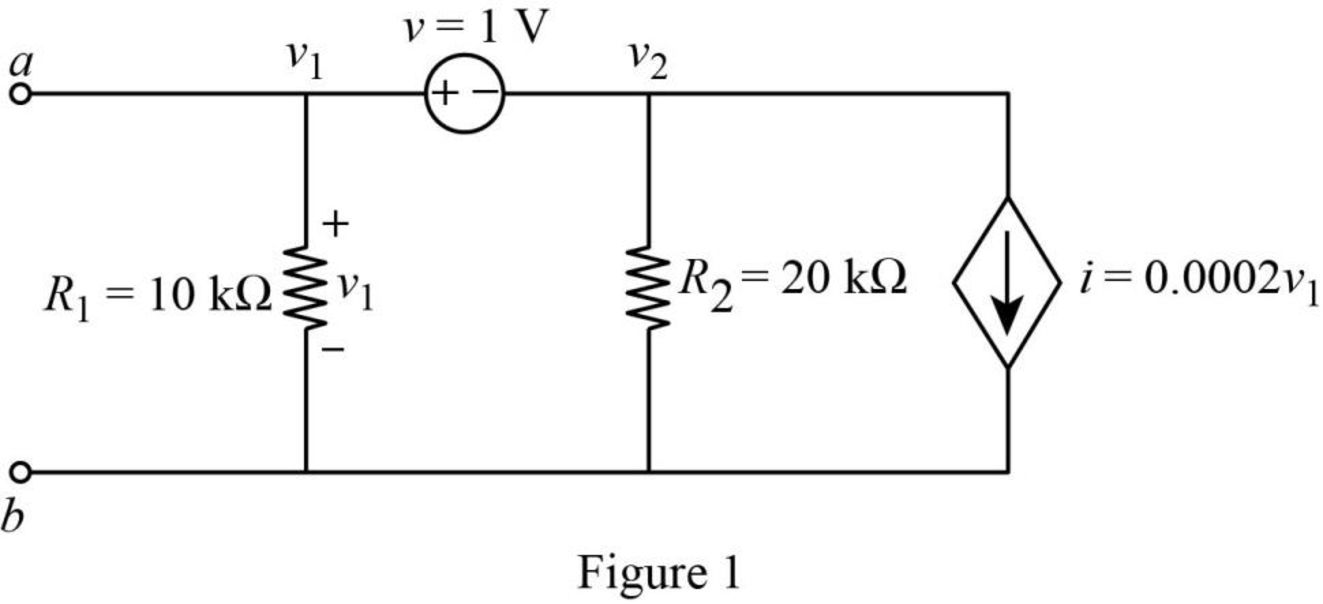
Refer to the redrawn Figure 1,
Apply Kirchhoff’s current law at node 1.
Here,
Substitute
Rearrange for
Rearrange for
Apply Kirchhoff’s voltage law between node 1 and 2.
Substitute
Rearrange for
So, the Thevenin voltage is
The redrawn circuit diagram is given in Figure 2,
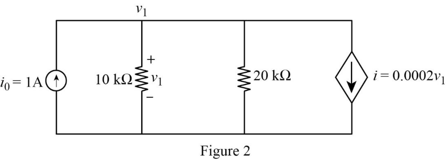
Refer to the redrawn Figure 2.
Apply Kirchhoff’s current law at node 1.
Here,
Substitute
Rearrange for
The expression for the Thevenin equivalent resistance is as follows,
Here,
Substitute
The redrawn circuit diagram is given in Figure 3,
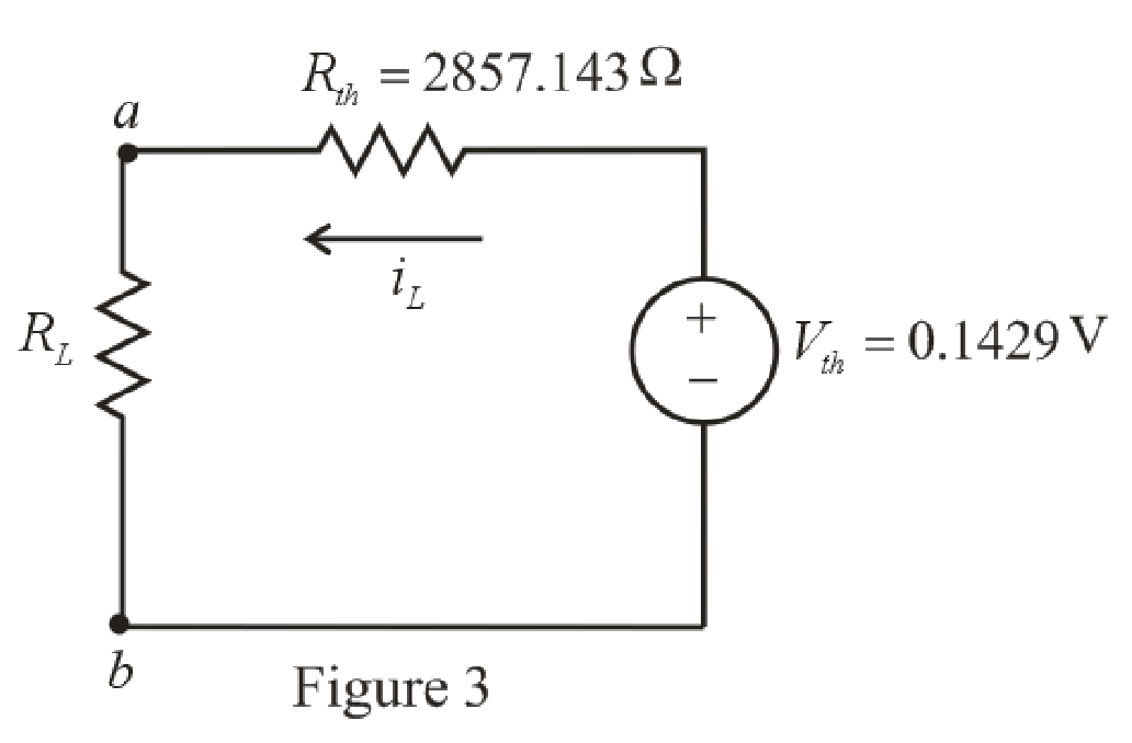
Refer to the redrawn Figure 3,
The expression for the current flowing in the circuit is as follows.
Here,
Substitute
Substitute
Conclusion:
Thus, the power dissipated by
(b)
The power dissipated by
(b)
Answer to Problem 41E
The power dissipated by
Explanation of Solution
Given Data:
The load resistance is
Calculation:
Refer to the redrawn Figure 3,
Substitute
Substitute
Conclusion:
Thus, the power dissipated by
(c)
The power dissipated by
(c)
Answer to Problem 41E
The power dissipated by
Explanation of Solution
Given Data:
The load resistance is
Calculation:
Refer to the redrawn Figure 3,
Substitute
Substitute
Conclusion:
Thus, the power dissipated by
Want to see more full solutions like this?
Chapter 5 Solutions
Loose Leaf for Engineering Circuit Analysis Format: Loose-leaf


- Describe functionalities of the “Battery Management System” and explain how the cell balancing is performed by the BMS.arrow_forwardPlease answer handwritten, do not use chat gbtarrow_forward1) The parameters for circuit in Figure 1 are ẞ₁ = 120, B2=80, VBE1 (On) = VBE2 (on) = 0.7 V and VA1 = VA2 = ∞0. a) Find the collector current in each transistor. b) Find the small signal voltage gain Av = Vo/Vs. c) Find the I/O resistance. Rib 5V. Figure 1 Q₁ 0.5 k Vcc=9V Q2 R ww 50 Ωarrow_forward
- 3) In the circuit in Figure 3, the Transistor parameters are VTN = 0.8 V and Kn = 0.5 mA/V2. Calculate ID, VGS, and VDS. VDD = 10 V Κ = 32 ΚΩ Κρ=4ΚΩ R2 = 18 ΚΩ Rs = 2k Figure 3arrow_forward2) Consider the circuit in Figure 2, The transistor parameters are VTP = -0.8 V and Kp = 0.5 mA/V2. Determine ID, VSG and VSD.arrow_forwardFor the circuit shown, let V₁ = 12 V, Is1 = 2A, Is2 = 4A, R₁ = 2, R2 = 4, and R3 = 6. Determine the current Io using Mesh method as follows: 1. Choose all meshes that must be included, if any, to construct the supermesh. 11, 13 O 11, 12 O 12, 13, 11 12, 13 O none of the above 2. Consider mesh (loop) iz, write the corresponding expression in terms of mesh currents i₁, 12, 13 as of the form (R11 · i₁ + R₁2 · 2 + R₁3-13 = V₁), then enter the corresponding values: R11 R12 R13 Ω Ω Ω V V₁₂ 3. Solve the above equation to determine then lo : 10 = Ist A R₁ ww ww R₂ + V₁ 1, R3 The relative tolerance for this problem is 7%. ww IS2arrow_forward
- Enter the matrix values (numerical) to solve for mesh-currents i₁, iz and 13, for the circuit shown, using Mesh method. In the matrix, row 1, row 2, and row 3 correspond to i₁, 12 and 13, current expressions, respectively. Let Vs=15, R₁ =50, R₂-32, R3-8, R4-17, R5-29, and R=41. [R11 R12 R13 The matrix values are shown here: R21 R22 R23 = V₂ R31 R32 R33 [V3] The relative tolerance for this problem is 5%. R1 Loop i₁ R11 + Vs Ω R12 Ω R13 Ω V V₁= Loop 12 R21 Ω R22 Ω R23 Ω V V₂ Loop 13 Ω R31 R32 Ω R33 Ω V3= V R2 R4 R3 R5 R6arrow_forwardFor circuit shown, use Mesh method to find the voltage Vo as follows. Enter, in the matrix format, as below, the loop currents, where row 1, and row 2, correspond to i₁, and i2 loop current expressions, respectively. Let Vs1-5, Vs2-15, R₁=5, R₂=2, and R3=8. The matrix values are shown here: [R11 R12 21 R21 R22 Rx - M - M iz = The relative tolerance for this problem is 5%. Vst (+- R1 ww Loop i₁ R115 G12 V₁ = Loop 12 R21 R22 V₂= Ω C C Ω V Ω 02 C V R₂ ww VS2 + Ry ww + Vo Use Cramer's rule (matrix), substitution, or any other method to calculate the voltages:arrow_forward= = For the circuit shown, let V, 15 V, I, 4A, R₁ =5, R₂ 10, R3 10, and R4 5. Determine the output voltage Vo as follows All resistor values are in ohms. 1. Identify the supermesh and write its corresponding Mesh equation. Provide your expression in terms of the shown mesh current i₁, and 12 of the form (R11 · 11+ R12 · 12 = V₁), then enter the corresponding values: R11 Ω R12 V₁= V Ω 2. Use the above equation, and supermesh inner expression to calculate i₂: i₂- Find Vo V₁ = A V R₁ www M R3 ww V R4 V₁ 0 IS R₁ The relative tolerance for this problem is 7 %. 0arrow_forward
 Introductory Circuit Analysis (13th Edition)Electrical EngineeringISBN:9780133923605Author:Robert L. BoylestadPublisher:PEARSON
 Delmar's Standard Textbook Of ElectricityElectrical EngineeringISBN:9781337900348Author:Stephen L. HermanPublisher:Cengage Learning
 Programmable Logic ControllersElectrical EngineeringISBN:9780073373843Author:Frank D. PetruzellaPublisher:McGraw-Hill Education
 Fundamentals of Electric CircuitsElectrical EngineeringISBN:9780078028229Author:Charles K Alexander, Matthew SadikuPublisher:McGraw-Hill Education
 Electric Circuits. (11th Edition)Electrical EngineeringISBN:9780134746968Author:James W. Nilsson, Susan RiedelPublisher:PEARSON
 Engineering ElectromagneticsElectrical EngineeringISBN:9780078028151Author:Hayt, William H. (william Hart), Jr, BUCK, John A.Publisher:Mcgraw-hill Education,