Loose Leaf for Engineering Circuit Analysis Format: Loose-leaf
9th Edition
ISBN: 9781259989452
Author: Hayt
Publisher: Mcgraw Hill Publishers
bartleby

Concept explainers

bartleby

Videos

Question
Book Icon
Chapter 5, Problem 63E

(a)

To determine

Find the two-component Thevenin equivalent of the network

(a)

Expert Solution
Check Mark

Answer to Problem 63E

The Thevenin equivalent resistance is 6.098 Ω and the Thevenin voltage is 0.6067 V.

Explanation of Solution

Formula used:

The expression for the equivalent resistor when resistors are connected in series is as follows:

Req=R1+R2+......+RN (1)

Here,

R1, R2,…, RN are the resistances.

The expression for the equivalent resistor when resistors are connected in parallel is as follows:

1Req=1R1+1R2+......+1RN (2)

Here,

R1, R2,…, RN are the resistances.

The Y-network and Δ-network circuit diagram is given in Figure 1.

Loose Leaf for Engineering Circuit Analysis Format: Loose-leaf, Chapter 5, Problem 63E , additional homework tip  1o

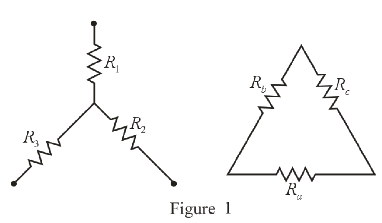
Refer to the redrawn Figure 1:

The expression for the conversion of Δ-network into Y-network is as follows:

R1=RbRcRa+Rb+Rc (3)

R2=RaRcRa+Rb+Rc (4)

R3=RaRbRa+Rb+Rc (5)

Here,

R1, R2 and R3 are the resistors connected in Y-network and

Ra, Rb and Rc are the resistors connected in Δ-network.

Calculation:

To find equivalent resistance of a circuit the independent voltage source is replaced by short circuit

The redrawn circuit diagram is given in Figure 2:

Loose Leaf for Engineering Circuit Analysis Format: Loose-leaf, Chapter 5, Problem 63E , additional homework tip  2

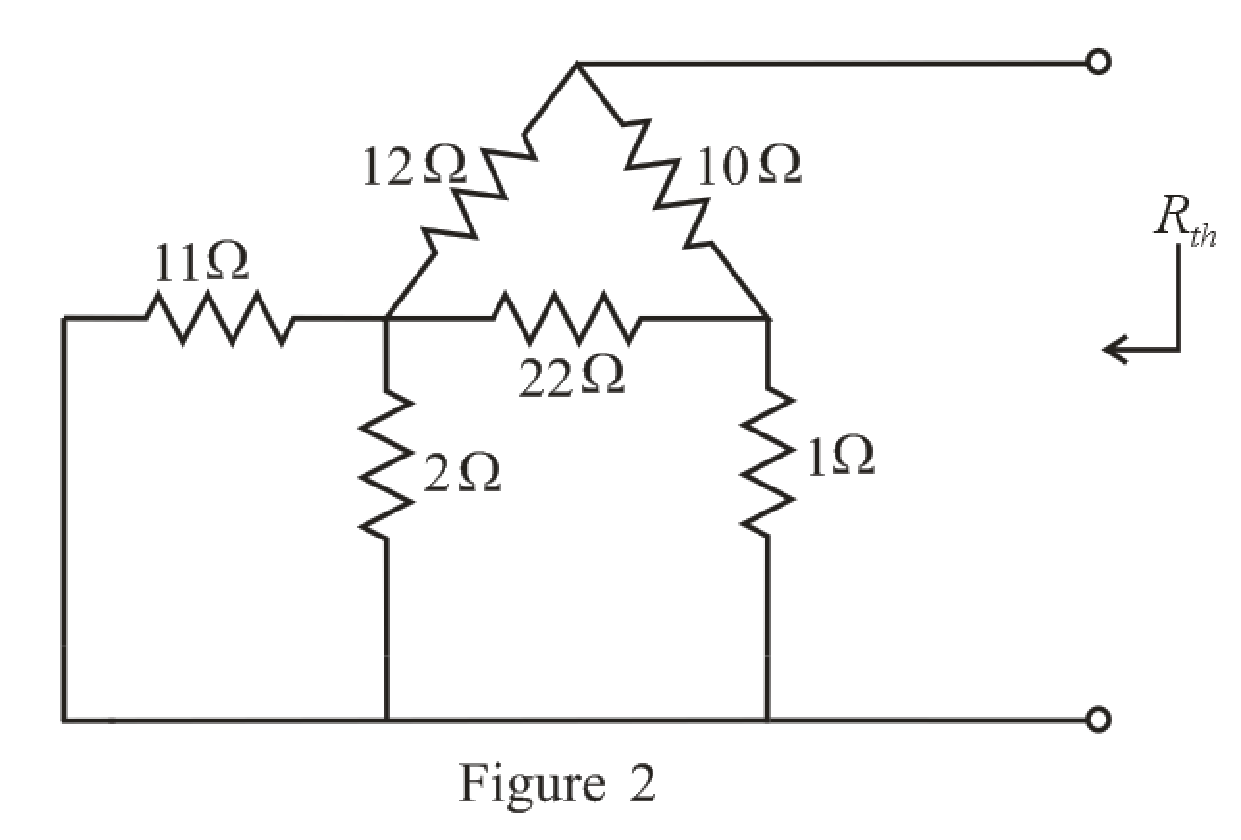
Refer to the redrawn Figure 2:

11 Ω and Ω resistor are connected in parallel.

Substitute 11 Ω for R1 and Ω for R2 equation (2):

1Req=111 Ω+1Ω=1322 Ω

Rearrange the equation for Req:

Req=2213 Ω=1.69 Ω

The simplified circuit diagram is given in Figure 3:

Loose Leaf for Engineering Circuit Analysis Format: Loose-leaf, Chapter 5, Problem 63E , additional homework tip  3

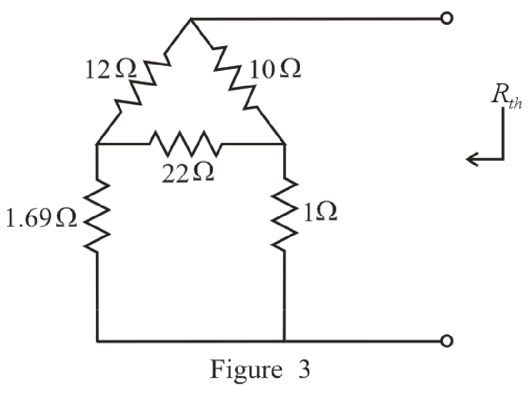
Refer to the redrawn Figure 3:

22 Ω, 1 Ω and Ω resistors are connected in Δ-network.

Substitute 22 Ω for Ra, 1 Ω for Rb and 1.69 Ω for Rc in equation (3):

R1=(1.69 Ω)(Ω)22 Ω+1 Ω+1.69 Ω=1.6924.69 Ω=0.0684 Ω

Substitute 22 Ω for Ra, 1 Ω for Rb and 1.69 Ω for Rc in equation (3):

R2=(1.69 Ω)(22 Ω)22 Ω+1 Ω+1.69 Ω=37.1824.69 Ω=1.51 Ω

Substitute 22 Ω for Ra, 1 Ω for Rb and 1.69 Ω for Rc in equation (3):

R3=(22 Ω)(Ω)22 Ω+1 Ω+1.69 Ω=2224.69 Ω=0.891 Ω

The simplified circuit diagram is given in Figure 4.

Loose Leaf for Engineering Circuit Analysis Format: Loose-leaf, Chapter 5, Problem 63E , additional homework tip  4

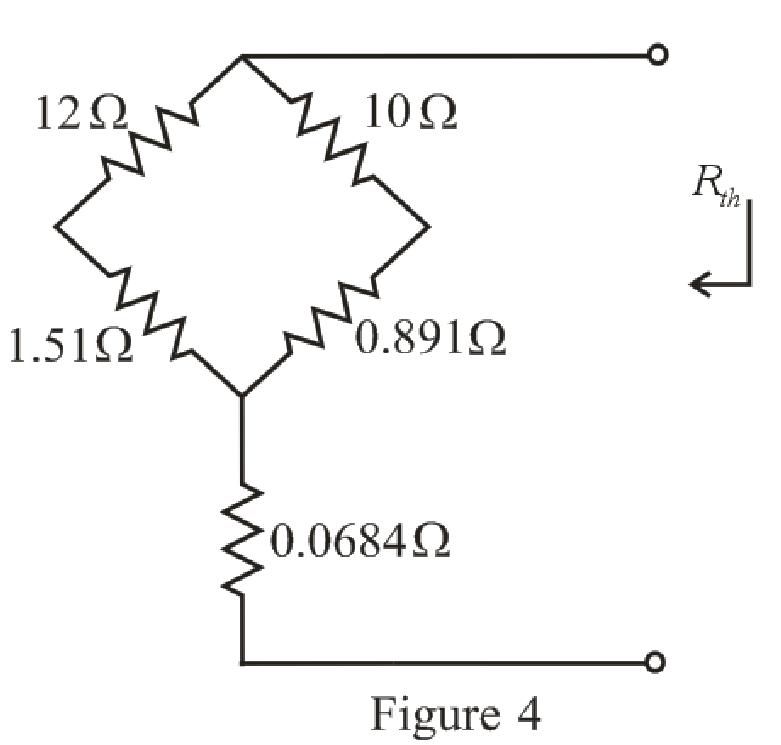
Refer to the redrawn Figure 4:

1.51 Ω and 12 Ω resistor are connected in series.

Substitute 1.51 Ω for R1 and 12 Ω for R2 equation (1):

Req=1.51 Ω+12Ω=13.51 Ω

0.891 Ω and 10 Ω resistor are connected in series.

Substitute 0.891 Ω for R1 and 10 Ω for R2 equation (1):

Req=0.891 Ω+10 Ω=10.891 Ω

13.51 Ω and 10.891 Ω resistor are connected in parallel.

Substitute 13.51 Ω for R1 and 10.891 Ω for R2 equation (2).

1Req=113.51 Ω+110.891 Ω=0.16584 Ω

Rearrange the equation for Req.

Req=10.16584Ω=6.0299 Ω

The simplified circuit diagram is given in Figure 5.

Loose Leaf for Engineering Circuit Analysis Format: Loose-leaf, Chapter 5, Problem 63E , additional homework tip  5

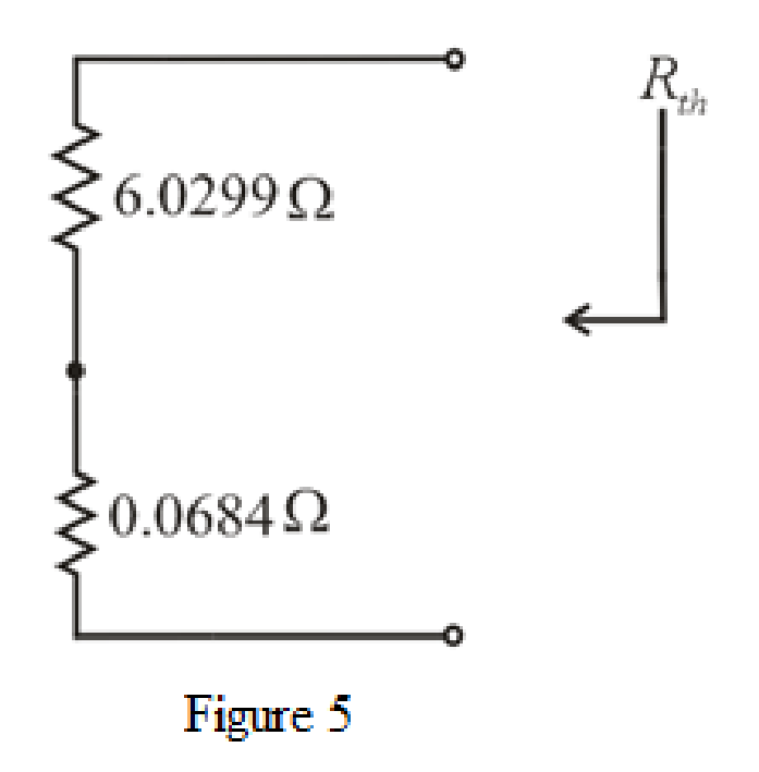
Refer to the redrawn Figure 5:

6.0299 Ω and 0.0684 Ω resistor are connected in series.

Substitute 6.0299 Ω for R1 and 0.0684 Ω for R2 equation (1):

Req=6.0299 Ω+0.0684 Ω=6.098 Ω

The simplified circuit diagram is given in Figure 6.

Loose Leaf for Engineering Circuit Analysis Format: Loose-leaf, Chapter 5, Problem 63E , additional homework tip  6

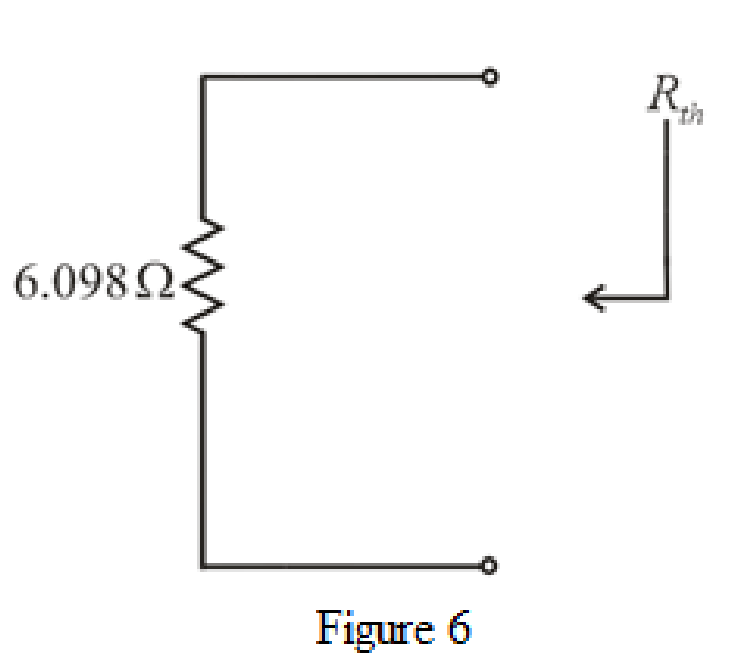
Refer to the redrawn Figure 6:

So, the Thevenin equivalent resistance is 6.098 Ω.

The redrawn circuit diagram is given in Figure 7.

Loose Leaf for Engineering Circuit Analysis Format: Loose-leaf, Chapter 5, Problem 63E , additional homework tip  7

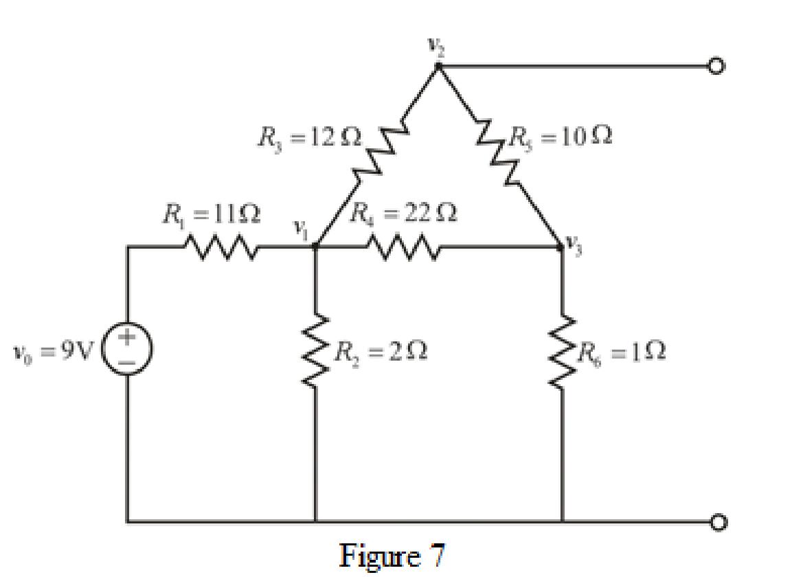
Refer to the redrawn Figure 7:

Apply KCL at node 1:

v1+voR1+v1R2+v1v2R3+v1v3R4=0 A (6)

Here,

v1 is the voltage at node 1,

v2 is the voltage at node 2,

v3 is the voltage at node 3,

vo is the voltage of 9 V independent source,

R1 is the resistance of 11 Ω resistor,

R2 is the resistance of 2 Ω resistor,

R3 is the resistance of 12 Ω resistor and

R4 is the resistance of 22 Ω resistor.

Substitute 9 V for vo, 11 Ω for R1, 2 Ω for R2, 12 Ω for R3 and 22 Ω for R4 in equation (7):

v1+9 V11 Ω+v1Ω+v1v212 Ω+v1v322 Ω=0 A12v1+108 V+66v1+11v111v2+6v16v3132 Ω=0 A95v1+108 V11v26v3132 Ω=0 A

Rearrange for v1, v2 and v3.

95v1+108 V11v26v3=0 V

95v111v26v3=108 V (7)

Apply KCL at node 2:

v2v1R3+v2v3R5=0 A (8)

Here,

R5 is the resistance of 10 Ω resistor.

Substitute 12 Ω for R3 and 10 Ω for R5 in equation (8):

v2v112 Ω+v2v310 Ω=0 A5v25v1+6v26v360 Ω=0 A11v25v16v360 Ω=0 A

Rearrange for v1, v2 and v3:

5v1+11v26v3=0 V (9)

Apply KCL at node 3:

v3v1R4+v3v2R5+v3R6=0 A (10)

Here,

R6 is the resistance of 1 Ω resistor.

Substitute 22 Ω for R4, 10 Ω for R5 and 1 Ω for R6 in equation (10):

v3v122 Ω+v3v210 Ω+v3Ω=0 A5v35v1+11v311v2+110v3110 Ω=0 A5v111v2+126v3110 Ω=0 A

Rearrange for v1, v2 and v3,

5v111v2+126v3=0 V (11)

The equations (7), (9) and (11) can be written in matrix form as:

(951165116511126)(v1v2v3)=(10800)

Therefore, by Cramer’s rule,

The determinant of the coefficient matrix is as follows:

Δ=|951165116511126|=117480

The 1st determinant is as follows:

Δ1=|1081160116011126|=142560

The 2nd determinant is as follows:

Δ2=|95108650650126|=71280

The 3rd determinant is as follows:

Δ3=|951110851105110|=11880

Simplify for v1.

v1=Δ1Δ=142560117480=1.213

Simplify for v2.

v2=Δ2Δ=71280117480=0.6067 V

Simplify for v3.

v3=Δ3Δ=11880117480=0.1011 V

So, the Thevenin voltage vTH is 0.6067 V.

Conclusion:

Thus, the Thevenin equivalent resistance is 6.098 Ω and the Thevenin voltage is,

0.6067 V.

(b)

To determine

Find the power dissipated by a 1 Ω resistor connected between the open terminals.

(b)

Expert Solution
Check Mark

Answer to Problem 63E

Thepower dissipated by a 1 Ω resistor connected between the open terminals is 7.306 mW.

Explanation of Solution

Given Data:

The load resistance is 1 Ω.

Formula used:

The expression for the power dissipated by a resistor is as follows:

p=(iL)2RL (11)

Here,

p is the power dissipated by a  resistor,

iL is the current flowing through the load resistor and

RL is the load resistance

Calculation:

The redrawn circuit diagram is given in Figure 8.

Loose Leaf for Engineering Circuit Analysis Format: Loose-leaf, Chapter 5, Problem 63E , additional homework tip  8

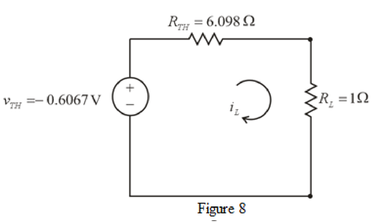
Refer to the redrawn Figure 8:

The expression for the current flowing in the circuit is as follows:

iL=vTHRTH+RL (12)

Here,

vTH is the Thevenin voltage of the circuit and

RTH is the Thevenin resistance of the circuit.

Substitute 6.098 Ω for RTH, 0.6067 V for vTh and 1 Ω for RL in equation (12):

iL=0.6067 V6.098 Ω+1 Ω=0.08547 A

Substitute 0.08547 A for iL and 1 Ω for RL in equation (11):

p=(0.08547 A)2(1 Ω)=7.306×10³ W=7.306 mW                                                           {103 W=1 mW}

Conclusion:

Thus, the power dissipated by a 1 Ω resistor connected between the open terminals is 7.306 mW.

Want to see more full solutions like this?

Subscribe now to access step-by-step solutions to millions of textbook problems written by subject matter experts!
Students have asked these similar questions
1. For the following logic gates: a. Write a Truth Table and logic equation? A Y A A. Y A Y "0" A A neotoof "0"> Day Y "1" A ADY DY A B DD A B b. What each of these gates represent? 2. Connect and draw the following digital logic equations: a. Y=X+1 b. Y=X+X' = \ c. Y=X X' d. Y=X 0 e. Y=XX' f. Y=XOX 3. Prove that: a. X(Y+Z)=XY+XZ b. X+YZ=(X+Y)(X+Z) c. (X+Y)'=X'Y' d. (XY)'=X'+Y e. X+XY=X f. X(X+Y)=X
I need help with this problem and an step by step explanation of the solution from the image described below. (Introduction to Signals and Systems: Spectrum Representation)
I need help with this problem and an step by step explanation of the solution from the image described below. (Introduction to Signals and Systems: A complex Numbers)

Chapter 5 Solutions

Loose Leaf for Engineering Circuit Analysis Format: Loose-leaf

Ch. 5.5 - Prob. 11PCh. 5 - Linear systems are so easy to work with that...Ch. 5 - Prob. 2ECh. 5 - Prob. 3ECh. 5 - (a) Employ superposition to determine the current...Ch. 5 - (a) Using superposition to consider each source...Ch. 5 - (a) Determine the individual contributions of each...Ch. 5 - (a) Determine the individual contributions of each...Ch. 5 - After studying the circuit of Fig. 5.53, change...Ch. 5 - Consider the three circuits shown in Fig. 5.54....Ch. 5 - (a) Using superposition, determine the voltage...Ch. 5 - Employ superposition principles to obtain a value...Ch. 5 - (a) Employ superposition to determine the...Ch. 5 - Perform an appropriate source transformation on...Ch. 5 - (a) For the circuit of Fig. 5.59, plot iL versus...Ch. 5 - Determine the current labeled I in the circuit of...Ch. 5 - Verify that the power absorbed by the 7 resistor...Ch. 5 - (a) Determine the current labeled i in the circuit...Ch. 5 - (a) Using repeated source transformations, reduce...Ch. 5 - Prob. 19ECh. 5 - (a) Making use of repeated source transformations,...Ch. 5 - Prob. 21ECh. 5 - (a) With the assistance of source transformations,...Ch. 5 - For the circuit in Fig. 5.67 transform all...Ch. 5 - Prob. 24ECh. 5 - (a) Referring to Fig. 5.69, determine the Thevenin...Ch. 5 - (a) With respect to the circuit depicted in Fig....Ch. 5 - (a) Obtain the Norton equivalent of the network...Ch. 5 - (a) Determine the Thevenin equivalent of the...Ch. 5 - Referring to the circuit of Fig. 5.71: (a)...Ch. 5 - Prob. 30ECh. 5 - (a) Employ Thvenins theorem to obtain a...Ch. 5 - Prob. 32ECh. 5 - Determine the Norton equivalent of the circuit...Ch. 5 - For the circuit of Fig. 5.75: (a) Employ Nortons...Ch. 5 - (a) Obtain a value for the Thvenin equivalent...Ch. 5 - Prob. 36ECh. 5 - Obtain a value for the Thvenin equivalent...Ch. 5 - With regard to the network depicted in Fig. 5.79,...Ch. 5 - Determine the Thvenin and Norton equivalents of...Ch. 5 - Determine the Norton equivalent of the circuit...Ch. 5 - Prob. 41ECh. 5 - Determine the Thvenin and Norton equivalents of...Ch. 5 - Prob. 43ECh. 5 - Prob. 44ECh. 5 - Prob. 45ECh. 5 - (a) For the simple circuit of Fig. 5.87, find the...Ch. 5 - For the circuit drawn in Fig. 5.88, (a) determine...Ch. 5 - Study the circuit of Fig. 5.89. (a) Determine the...Ch. 5 - Prob. 49ECh. 5 - Prob. 50ECh. 5 - With reference to the circuit of Fig. 5.91, (a)...Ch. 5 - Prob. 52ECh. 5 - Select a value for RL in Fig. 5.93 such that it...Ch. 5 - Determine what value of resistance would absorb...Ch. 5 - Derive the equations required to convert from a...Ch. 5 - Convert the - (or "-") connected networks in Fig....Ch. 5 - Convert the Y-(or T-) connected networks in Fig....Ch. 5 - For the network of Fig. 5.97, select a value of R...Ch. 5 - For the network of Fig. 5.98, select a value of R...Ch. 5 - Prob. 60ECh. 5 - Calculate Rin as indicated in Fig.5.100. FIGURE...Ch. 5 - Employ Y conversion techniques as appropriate to...Ch. 5 - Prob. 63ECh. 5 - (a) Use appropriate techniques to obtain both the...Ch. 5 - (a) For the network in Fig. 5.104, replace the...Ch. 5 - Prob. 66ECh. 5 - Prob. 67ECh. 5 - A 2.57 load is connected between terminals a and...Ch. 5 - A load resistor is connected across the open...Ch. 5 - A backup is required for the circuit depicted in...Ch. 5 - (a) Explain in general terms how source...Ch. 5 - The load resistor in Fig. 5.108 can safely...Ch. 5 - Prob. 74ECh. 5 - As part of a security system, a very thin 100 ...Ch. 5 - With respect to the circuit in Fig. 5.90, (a)...
Knowledge Booster
Background pattern image
Electrical Engineering
Learn more about
Need a deep-dive on the concept behind this application? Look no further. Learn more about this topic, electrical-engineering and related others by exploring similar questions and additional content below.
Recommended textbooks for you
Text book image
Introductory Circuit Analysis (13th Edition)
Electrical Engineering
ISBN:9780133923605
Author:Robert L. Boylestad
Publisher:PEARSON
Text book image
Delmar's Standard Textbook Of Electricity
Electrical Engineering
ISBN:9781337900348
Author:Stephen L. Herman
Publisher:Cengage Learning
Text book image
Programmable Logic Controllers
Electrical Engineering
ISBN:9780073373843
Author:Frank D. Petruzella
Publisher:McGraw-Hill Education
Text book image
Fundamentals of Electric Circuits
Electrical Engineering
ISBN:9780078028229
Author:Charles K Alexander, Matthew Sadiku
Publisher:McGraw-Hill Education
Text book image
Electric Circuits. (11th Edition)
Electrical Engineering
ISBN:9780134746968
Author:James W. Nilsson, Susan Riedel
Publisher:PEARSON
Text book image
Engineering Electromagnetics
Electrical Engineering
ISBN:9780078028151
Author:Hayt, William H. (william Hart), Jr, BUCK, John A.
Publisher:Mcgraw-hill Education,
Z Parameters - Impedance Parameters; Author: Electrical Engineering Authority;https://www.youtube.com/watch?v=qoD4AoNmySA;License: Standard Youtube License