
Concept explainers
Videos
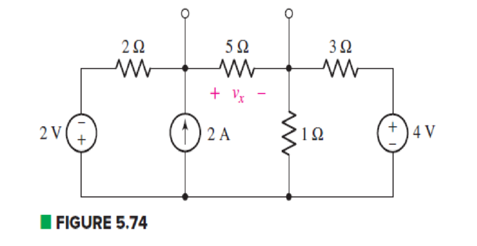
Determine the Norton equivalent of the circuit depicted in Fig. 5.74 as seen looking into the two open terminals. (b) Compute power dissipated in a 5 Ω resistor connected in parallel with the existing 5 Ω resistor. (c) Compute the current flowing through a short circuit connecting the two terminals.
(a)
Find the Norton equivalent of the circuit as seen looking into the two open terminals.
Answer to Problem 33E
The Norton current is
Explanation of Solution
Formula used:
The expression for voltage is as follows.
Here,
The expression for series combination of resistance is as follows.
Here,
The expression for parallel combination of resistance is as follows.
Here,
Calculation:
The circuit diagram is redrawn as shown in Figure 1.
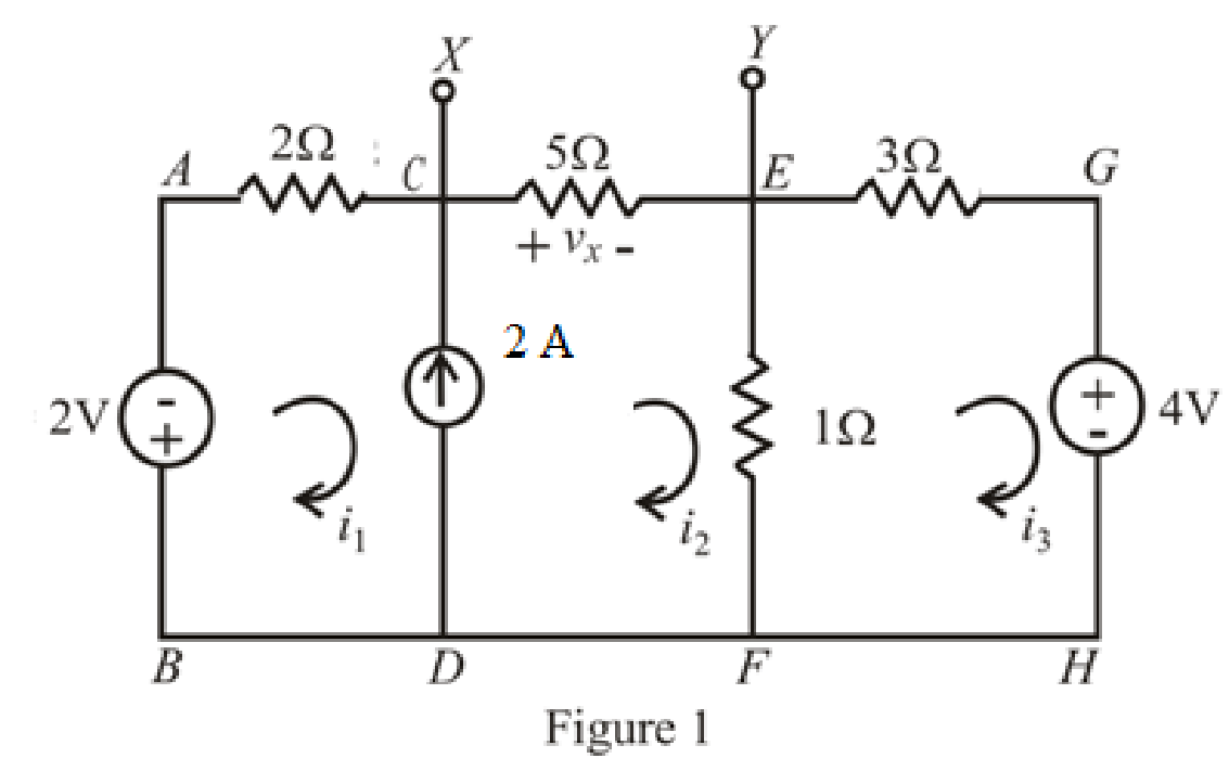
Refer to redrawn Figure 1,
The expression for KVL in super mesh
Here,
Substitute
The expression for KVL in mesh
Here,
Substitute
The expression for current
Here,
Substitute
Rearrange equations(5),(7) and (9).
The equations so formed can be written in matrix form as,
Therefore, by Cramer’s rule,
The determinant of coefficient matrix is as follows.
The 1st determinant is as follows.
The 2nd determinant is as follows,
The 3rd determinant is as follows.
Simplify for
Simplify for
Simplify for
Substitute
So, the Thevenin voltage is
The circuit diagram is redrawn as shown in Figure 2.
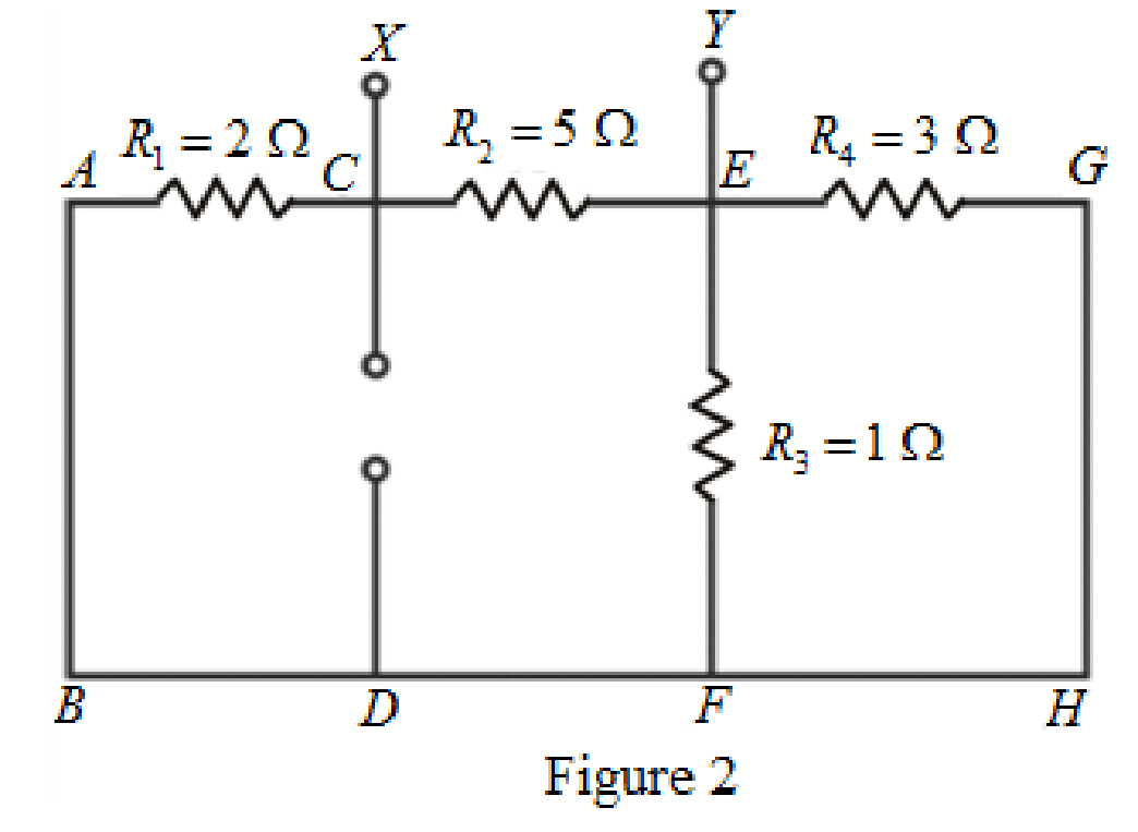
As
Rearrange for
The circuit diagram is redrawn as shown in Figure 3.
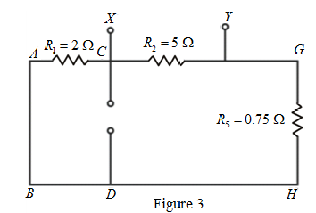
As
The circuit diagram is redrawn as shown in Figure 4.
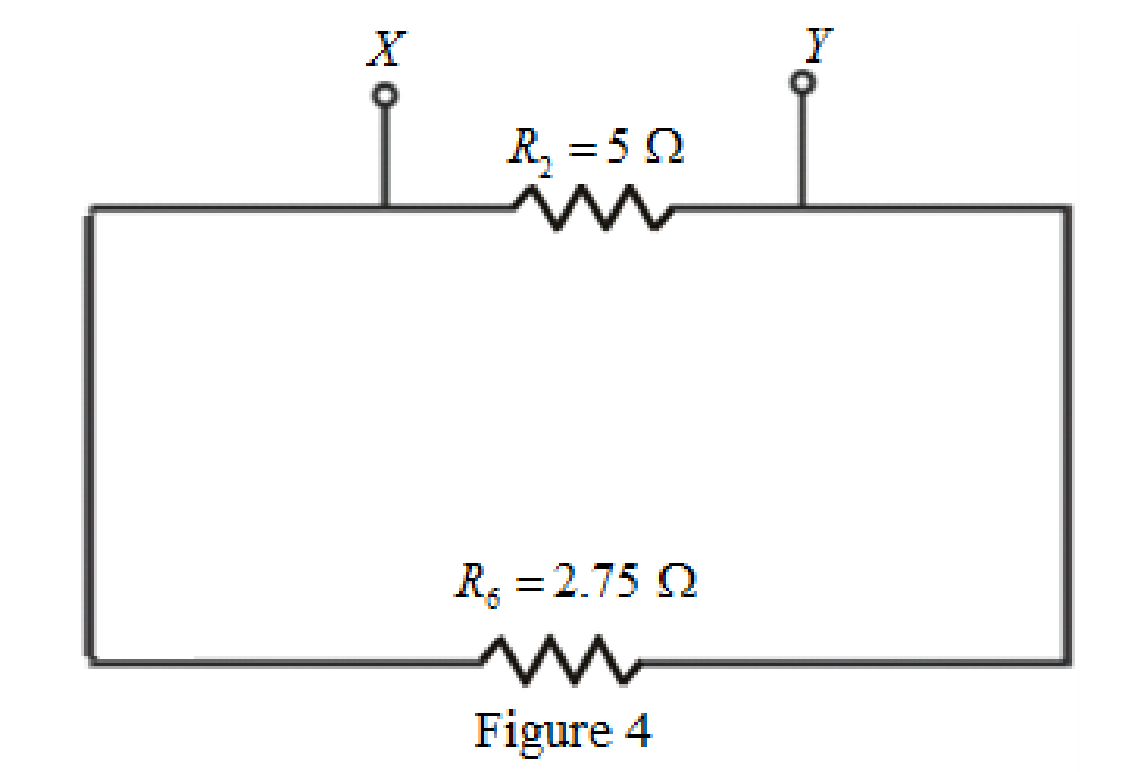
Refer to redrawn Figure 4,
As
Rearrange for
So, the Thevenin equivalent resistance across the branch
Thevenin equivalent resistance is same as the Norton equivalent resistance,
Hence,
The circuit diagram is redrawn as shown in Figure 5,
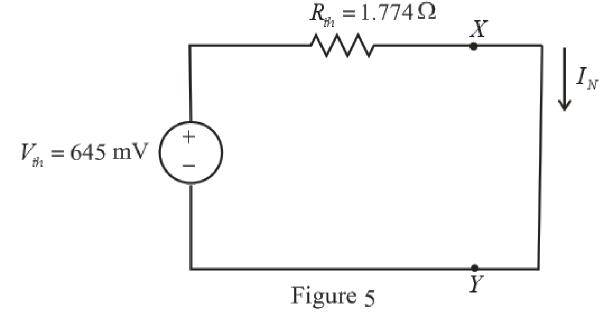
Refer to redrawn Figure 5,
Norton current is the current in the load resistor when load resistance is replaced by a short circuit.
The expression for the Norton current flowing in the circuit is as follows,
Here,
Substitute
Conclusion:
Thus the Norton current is
(b)
Find the power dissipated in a
Answer to Problem 33E
The power dissipated in a
Explanation of Solution
Given Data:
The load resistance is
Formula used:
The expression for the power dissipated in a resistor is as follows,
Here,
Calculation:
The circuit is drawn as shown in Figure 6,
Refer to redrawn Figure 6,
The simplified Norton equivalent of the circuit is drawn as shown in Figure 7,
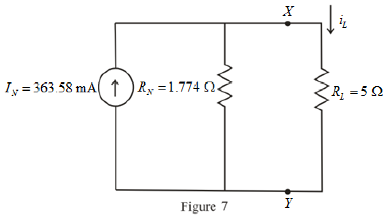
Refer to redrawn Figure 7,
The expression for the current flowing through the load is as follows,
Substitute
Substitute
Conclusion:
Thus, the power dissipated in a
(c)
Find the current flowing through a short circuit connecting the two terminals.
Answer to Problem 33E
The current flowing through a short circuit connecting the two terminals is
Explanation of Solution
Calculation:
The current flowing through a short circuit connecting the two terminals is Norton current which is
So, the current flowing through a short circuit connecting the two terminals is
Conclusion:
Thus, the current flowing through a short circuit connecting the two terminals is
Want to see more full solutions like this?
Chapter 5 Solutions
Loose Leaf for Engineering Circuit Analysis Format: Loose-leaf


- Given the following reaction system, where Xo is the input, i.e u(t) = k₁ × Xo: $Xo -> x1; k1*Xo x2; k2*x1 x1 2 x2 ->%; k3*x2^2 x2 ->; k4*x2 Xo 1; k1 = 0.4 k2 4.5; k3 = 0.75 k4= 0.2 a) Build the model in Tellurium and run a simulation. Compute the Jacobian at steady state using the method getFull Jacobian(). Make sure you are at steady state! b) Write out the values for n and p c) Write out the differential equations. d) Write out the state space representation in terms of the rate constants etc. e) Compute the values in the Jacobian matrix from d) by substituting the values of the rate constants etc and any data you need from the simulation. f) Confirm that the Jacobian you get in e) is the same as the one computed from the simulation in a). g) Is the system stable or not? If you find an eigenvalue of zero, that means the system is marginally stable. You can get the eigenvalues using the tellurium method r.getFullEigenvalues()arrow_forwardSolve by Pen and Paper not using chatgpt or AIarrow_forwardYou just got a job at Shin-Etsu Chemical growing Si crystals with different dopants. Howmuch Ga needs to be added to 800 kg of Si melt to achieve a 5-10 Ω.cm (measured at midheight) Si CZ crystal with the following characteristics: height: 7 ft, width: 12 inchesdiameter. Assume, angular rotation 10 RPM, melt viscosity 0.1 poise, pull velocity 2mm/min.a. Generate a plot of the doping distribution throughout the length of the crystal (CGa vs. fs ).b. If a second crystal were to be pulled out of the melt without replenishment of silicon nordopant what would be the average resistivity of this crystal (or resistivity at mid height)arrow_forward
- DO NOT USE AI OR CHAT GPT NEED HANDWRITTEN SOLUTIONarrow_forward7. Complete the following problems for the circuit below. (a) When VDD = 120V, What is the voltage drop V1 across the 7Ω resistor? (b) If the voltage source VDD is set to obtain I1 = 2A, find the value of VDD. (c) If I1 = 100A, What is the value of I2arrow_forwarda) In terms of n and p, how many state variables and how many inputs can you see in the system below? dx1 =x12x2 + 9u1 dt dx2 =x1+x3+3u2 dt dx3 = 4x1 +5x2 - 12x3 dt b) Derive the state space representation for the above system c) Determine whether the system is stable or not.arrow_forward
- Circuit Logic. Match each statement to the proper circuit. All circuits have been drawn with a light (L) to represent the load, whether it is a motor, bell, light, or any other load. In addition, each switch is illustrated as a pushbutton whether it is a maintained switch, momentary contact switch, pushbutton, switch-on target, or any other type of switch.arrow_forwarda) In terms of n and p, how many state variables and how many inputs can you see in the system below? dx1 = 4x1 = x2 dt dx2 =-3x12x2 +U1 dt b) Derive the state space representation for the above system c) Determine whether the system is stable or not.arrow_forwardmatch each statement to the proper circuit. All circuits have been drawn with a light (L) to represent the load, whether it is a motor, bell, light or any other load. In addition, each switch is illustrated as a push button whether it is maintained switch, momentary contact switch, pushbutton, switch-on target, or any other type of switch.arrow_forward
- a) In terms of n and p, how many state variables and how many inputs can you see in the system below? dx1 =-7x1 + x2 + 5u1 dt dx2 =-11x1+x3 + 2u1 dt dx3 = -8x16u1 dt b) Derive the state space representation for the above system c) Determine whether the system is stable or not.arrow_forwardQuestion 2 (20 points) a) In terms of n and p, how many state variables and how many inputs can you see in the system below? dx1 dt =x1- 2x2 dx2 = 3x1 - 4x2 dt b) Derive the state space representation for the above system c) Determine whether the system is stable or not.arrow_forwardStuck on the question. Please do not use AI, it will get the answer wrong.arrow_forward
 Introductory Circuit Analysis (13th Edition)Electrical EngineeringISBN:9780133923605Author:Robert L. BoylestadPublisher:PEARSON
 Delmar's Standard Textbook Of ElectricityElectrical EngineeringISBN:9781337900348Author:Stephen L. HermanPublisher:Cengage Learning
 Programmable Logic ControllersElectrical EngineeringISBN:9780073373843Author:Frank D. PetruzellaPublisher:McGraw-Hill Education
 Fundamentals of Electric CircuitsElectrical EngineeringISBN:9780078028229Author:Charles K Alexander, Matthew SadikuPublisher:McGraw-Hill Education
 Electric Circuits. (11th Edition)Electrical EngineeringISBN:9780134746968Author:James W. Nilsson, Susan RiedelPublisher:PEARSON
 Engineering ElectromagneticsElectrical EngineeringISBN:9780078028151Author:Hayt, William H. (william Hart), Jr, BUCK, John A.Publisher:Mcgraw-hill Education,