
Concept explainers
Videos
(a) Obtain a value for the Thévenin equivalent resistance seen looking into the open terminals of the circuit in Fig. 5.76 by first finding Voc and Isc. (b) Connect a 1 A test source to the open terminals of the original circuit after shorting the voltage source, and use this to obtain RTH. (c) Connect a 1 V test source to the open terminals of the original circuit after again zeroing the 2 V source, and use this now to obtain RTH.
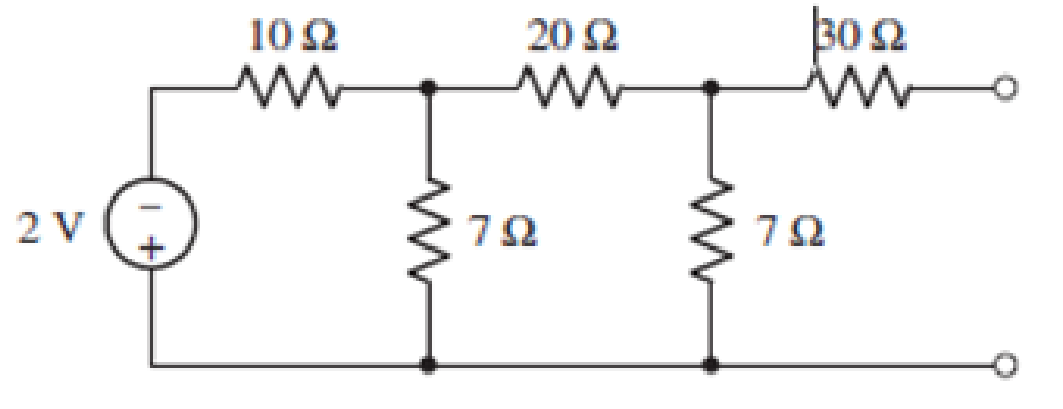
FIGURE 5.76
(a)
Find the value for the Thevenin’s equivalent resistance seen looking into the open terminals of the circuit by first finding
Answer to Problem 35E
The Thevenin’s equivalent resistance is
Explanation of Solution
Calculation:
The redrawn circuit diagram is given in Figure 1.
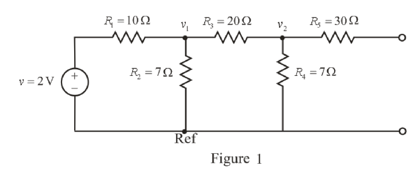
Apply KCL ay node 1,
Here,
Substitute
Rearrange for
Apply KCL at node 2,
Here,
Substitute
Rearrange for
Substitute
Rearrange for
Substitute
So, the voltage
The redrawn circuit diagram is given in Figure 2,
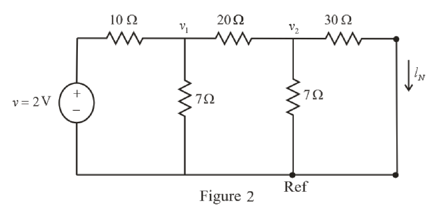
Refer to the redrawn Figure 2,
Apply KCL at node 1,
Substitute
Rearrange for
Apply KCL at node 2,
Here,
Substitute
Rearrange for
Substitute
The expression for the current flowing through
Here,
Substitute
So, the current
The expression for the Thevenin’s equivalent resistance is as follows,
Here,
Substitute
Conclusion:
Thus, the Thevenin’s equivalent resistance is
(b)
Connect a
Answer to Problem 35E
The Thevenin’s equivalent resistance is
Explanation of Solution
Calculation:
The redrawn circuit diagram is given in Figure 3,
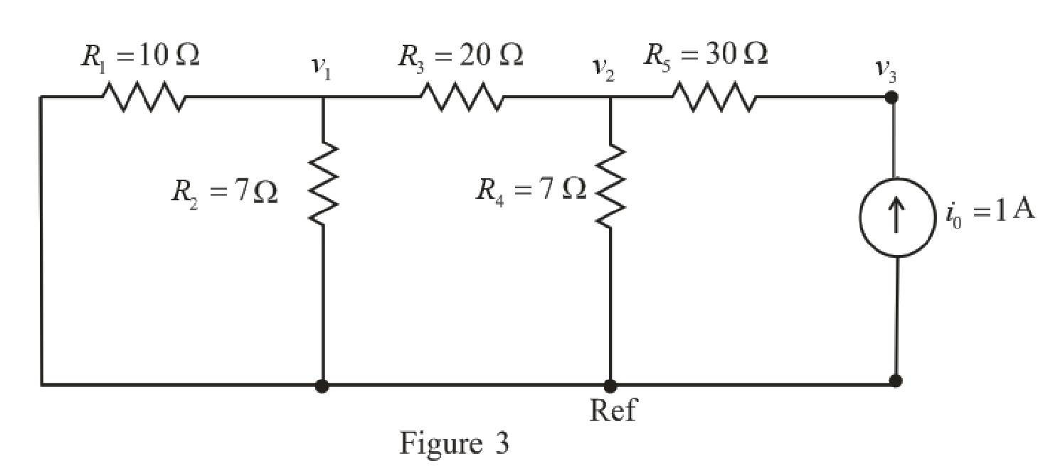
Refer to the redrawn Figure 3,
Apply KCL ay node 1,
Here,
Substitute
Rearrange for
Apply KCL at node 2,
Here,
Substitute
Rearrange for
The expression for the current flowing through
Here,
Substitute 1 A for
Rearrange for
Substitute
Substitute
Rearrange for
Substitute
The expression for the Thevenin’s equivalent resistance is as follows,
Here,
Substitute 35.43 V for
Conclusion:
Thus, the Thevenin’s equivalent resistance is
(c)
Connect a 1 V test source to the open terminals of the original circuit after again
zeroing the 2 V source, and use this now to obtain
Answer to Problem 35E
The Thevenin’s equivalent resistance is
Explanation of Solution
Calculation:
The redrawn circuit diagram is given in Figure 4,
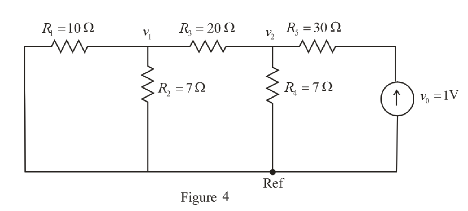
Refer to the redrawn Figure 4,
Apply KCL ay node 1,
Here,
Substitute
Rearrange for
Apply KCL at node 2,
Here,
Substitute
Rearrange for
Substitute
The expression for the Thevenin’s equivalent resistance is as follows,
Here,
Substitute 0.1532 V for
Conclusion:
Thus, the Thevenin’s equivalent resistance is
Want to see more full solutions like this?
Chapter 5 Solutions
Loose Leaf for Engineering Circuit Analysis Format: Loose-leaf


- 2-3) For each of the two periodic signals in the figures below, find the exponential Fourier series and sketch the magnitude and angle spectra. -5 ΟΙ 1 1- (a) (b) -20π -10x -π Π 10m 20m 1-arrow_forwardI need help with this problem and an explanation of the solution for the image described below. (Introduction to Signals and Systems)arrow_forwardIn the op-amp circuit shown in Fig. P8.32,uin(t) = 12cos(1000t) V,R = 10 k Ohm , RL = 5 k Ohm, and C = 1 μF. Determine the complexpower for each of the passive elements in the circuit. Isconservation of energy satisfied?arrow_forward
- 2-4) Similar to Lathi & Ding prob. 2.9-4 (a) For signal g(t)=t, find the exponential Fourier series to represent g(t) over the interval(0, 1). (b) Sketch the original signal g(t) and the everlasting signal g'(t) represented by the same Fourier series. (c) Verify Parseval's theorem [eq. (2.103b)] for g'(t), given that: = n 1 6arrow_forward8.24 In the circuit of Fig. P8.24, is(t) = 0.2sin105t A,R = 20 W, L = 0.1 mH, and C = 2 μF. Show that the sum ofthe complex powers for the three passive elements is equal to thecomplex power of the source.arrow_forward3. VEB (on) 0.7 V, VEC (sat) = 0.2 V, and ẞ = 150. RB = 50 kQ, Rc = 2 kQ, and Vcc = 5 V. a) Find the range of V₁ for the cut-off. Forward active, and saturation regions. (20 points) b) Draw the voltage transfer characteristic (VTC) graph. (10 points) Vcc VEB V₁ RB www 。 Vo Rc Figure 3arrow_forward
- 2-1) Lathi & Ding prob. 2.5-2 For the signals y(t) and x(t) shown below, find the component of the form y(t) contained in x(t). In other words, find the optimum value of c in the approximation x(t) = cy(t) so that the error signal energy is minimum. Also compute the error signal energy. y(t) x(t) 0 1 0 1arrow_forward1. Is1 = 2ls2 = 4 × 10-16 A, B₁ = ẞ2 = 100, and R₁ = 5 kQ. Find the VB such that lx = 1 mA. (30 points) R1 ww Q2 + VB Figure 1arrow_forward2-2) Lathi & Ding prob. 2.6-1 2.6-1 Find the correlation coefficient p between of signal x(t) and each of the four pulses g1(1), 82(1), 83(1), and g4(f) shown in Fig. P2.6-1. To provide maximum margin against the noise along the transmission path, which pair of pulses would you select for a binary communication? Figure P.2.6-1 x(f) (a) 8(1) (b) 82(1) (c) 1 1 sin 2πt sin 4πt -sin 2 0 0.707 83(1) 0 1 (d) 0 M P 0.707 84(1) (e) 0 0.5 -0.707arrow_forward
- 2. Determine the operation point and the small-signal model of Q₁ for each of the circuits shown in Fig. 2. Assume Is = 8 × 10-16 A, B = 100 and VA = ∞. a) 20 points b) 20 points 0.8 V RC 50 Ω + Vcc = 2.5 V 4A" Figure 2-a Rc1kQ + Vcc = 2.5 V Figure 2-barrow_forwardPlease explain in detail how to solve this question. Show detailed steps in terms of calculation and theory. thank youarrow_forwardPls show neat and whole solutionarrow_forward
 Introductory Circuit Analysis (13th Edition)Electrical EngineeringISBN:9780133923605Author:Robert L. BoylestadPublisher:PEARSON
 Delmar's Standard Textbook Of ElectricityElectrical EngineeringISBN:9781337900348Author:Stephen L. HermanPublisher:Cengage Learning
 Programmable Logic ControllersElectrical EngineeringISBN:9780073373843Author:Frank D. PetruzellaPublisher:McGraw-Hill Education
 Fundamentals of Electric CircuitsElectrical EngineeringISBN:9780078028229Author:Charles K Alexander, Matthew SadikuPublisher:McGraw-Hill Education
 Electric Circuits. (11th Edition)Electrical EngineeringISBN:9780134746968Author:James W. Nilsson, Susan RiedelPublisher:PEARSON
 Engineering ElectromagneticsElectrical EngineeringISBN:9780078028151Author:Hayt, William H. (william Hart), Jr, BUCK, John A.Publisher:Mcgraw-hill Education,