
Loose Leaf for Engineering Circuit Analysis Format: Loose-leaf
9th Edition
ISBN: 9781259989452
Author: Hayt
Publisher: Mcgraw Hill Publishers
expand_more
expand_more
format_list_bulleted
Concept explainers
Videos
Textbook Question
Chapter 5, Problem 29E
Referring to the circuit of Fig. 5.71: (a) Determine the Norton equivalent of the circuit by first finding Voc and Isc (defined as flowing into the positive reference terminal of Voc). (b) Connect a 1.7 kΩ resistor to the open terminals of your new network and calculate the power supplied to that resistor.
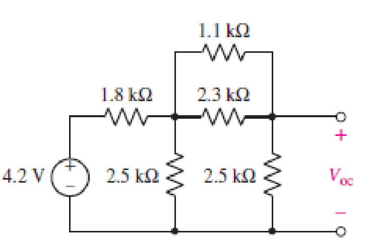
FIGURE 5.71
Expert Solution & Answer
Want to see the full answer?
Check out a sample textbook solution
Students have asked these similar questions
The MATLAB code is going well but the last part in bandpass, the legend that is supposed to tell the color of both lower and upper-frequency cutoff does not align with each other. As such I need help
My Matlab code:
% Define frequency range for the plot
f = logspace(1, 5, 500); % Frequency range from 10 Hz to 100 kHz
w = 2 * pi * f; % Angular frequency
% Parameters for the filters
R = 1e3; % Resistance in ohms (1 kΩ)
C = 1e-6; % Capacitance in farads (1 μF)
L = 0.1; % Inductance in henries (chosen for proper bandpass response)
% Compute cutoff frequencies
f_cutoff_RC = 1 / (2 * pi * R * C); % RC low-pass/high-pass cutoff
f_resonance = 1 / (2 * pi * sqrt(L * C)); % Resonant frequency of RLC
Q_factor = (1/R) * sqrt(L/C); % Quality factor of the circuit
% Band-pass filter cutoff frequencies
f_lower_cutoff = f_resonance / (sqrt(1 + 1/(4*Q_factor^2)) + 1/(2*Q_factor));
f_upper_cutoff = f_resonance / (sqrt(1 + 1/(4*Q_factor^2)) - 1/(2*Q_factor));
% Define Transfer Functions
H_low =…
1°
⑤
Aa
"Human-written solution required"
2. Using the characteristics of Fig. 6.11, determine ID for the following levels of VGs (with
VDS > VP):
a. VGs = 0V.
b. VGs=-1 V.
c. VGs -1.5 V.
d. VGS
-1.8 V.
e. VGS = -4 V.
f. VGs=-6V.
3. Using the results of problem 2 plot the transfer characteristics of ID vs. VGS-
4. a. Determine Vps for VGs = 0V and Ip = 6 mA using the characteristics of Fig. 6.11.
b. Using the results of part (a), calculate the resistance of the JFET for the region Ip = 0 to
6 mA for VGs =0V.
c. Determine Vps for VGS = -1 V and ID = 3 mA.
d. Using the results of part (c), calculate the resistance of the JFET for the region ID = 0 to
3 mA for VGs -1 V.
e. Determine Vps for VGs = -2 V and ID = 1.5 mA.
f. Using the results of part (e), calculate the resistance of the JFET for the region ID = 0 to
1.5 mA for VGS-2 V.
g. Defining the result of part (b) as ro, determine the resistance for VGs -1 V using
Eq. (6.1) and compare with the results of part (d).
h. Repeat part (g)…
①
Esterfication
+ R'on
R
Hydrolysis
OH
Alcohol
A.
0-R
Carboxylic
Acid
Ester
NOD-10
Chapter 5 Solutions
Loose Leaf for Engineering Circuit Analysis Format: Loose-leaf
Ch. 5.1 - For the circuit of Fig. 5.4, use superposition to...Ch. 5.2 - For the circuit of Fig. 5.7, use superposition to...Ch. 5.2 - For the circuit of Fig. 5.18, compute the current...Ch. 5.2 - For the circuit of Fig. 5.20, compute the voltage...Ch. 5.3 - Using repeated source transformations, determine...Ch. 5.3 - Use Thvenins theorem to find the current through...Ch. 5.3 - Determine the Thvenin and Norton equivalents of...Ch. 5.3 - Find the Thvenin equivalent for the network of...Ch. 5.3 - Find the Thvenin equivalent for the network of...Ch. 5.4 - Consider the circuit of Fig. 5.43. FIGURE 5.43...
Ch. 5.5 - Prob. 11PCh. 5 - Linear systems are so easy to work with that...Ch. 5 - Prob. 2ECh. 5 - Prob. 3ECh. 5 - (a) Employ superposition to determine the current...Ch. 5 - (a) Using superposition to consider each source...Ch. 5 - (a) Determine the individual contributions of each...Ch. 5 - (a) Determine the individual contributions of each...Ch. 5 - After studying the circuit of Fig. 5.53, change...Ch. 5 - Consider the three circuits shown in Fig. 5.54....Ch. 5 - (a) Using superposition, determine the voltage...Ch. 5 - Employ superposition principles to obtain a value...Ch. 5 - (a) Employ superposition to determine the...Ch. 5 - Perform an appropriate source transformation on...Ch. 5 - (a) For the circuit of Fig. 5.59, plot iL versus...Ch. 5 - Determine the current labeled I in the circuit of...Ch. 5 - Verify that the power absorbed by the 7 resistor...Ch. 5 - (a) Determine the current labeled i in the circuit...Ch. 5 - (a) Using repeated source transformations, reduce...Ch. 5 - Prob. 19ECh. 5 - (a) Making use of repeated source transformations,...Ch. 5 - Prob. 21ECh. 5 - (a) With the assistance of source transformations,...Ch. 5 - For the circuit in Fig. 5.67 transform all...Ch. 5 - Prob. 24ECh. 5 - (a) Referring to Fig. 5.69, determine the Thevenin...Ch. 5 - (a) With respect to the circuit depicted in Fig....Ch. 5 - (a) Obtain the Norton equivalent of the network...Ch. 5 - (a) Determine the Thevenin equivalent of the...Ch. 5 - Referring to the circuit of Fig. 5.71: (a)...Ch. 5 - Prob. 30ECh. 5 - (a) Employ Thvenins theorem to obtain a...Ch. 5 - Prob. 32ECh. 5 - Determine the Norton equivalent of the circuit...Ch. 5 - For the circuit of Fig. 5.75: (a) Employ Nortons...Ch. 5 - (a) Obtain a value for the Thvenin equivalent...Ch. 5 - Prob. 36ECh. 5 - Obtain a value for the Thvenin equivalent...Ch. 5 - With regard to the network depicted in Fig. 5.79,...Ch. 5 - Determine the Thvenin and Norton equivalents of...Ch. 5 - Determine the Norton equivalent of the circuit...Ch. 5 - Prob. 41ECh. 5 - Determine the Thvenin and Norton equivalents of...Ch. 5 - Prob. 43ECh. 5 - Prob. 44ECh. 5 - Prob. 45ECh. 5 - (a) For the simple circuit of Fig. 5.87, find the...Ch. 5 - For the circuit drawn in Fig. 5.88, (a) determine...Ch. 5 - Study the circuit of Fig. 5.89. (a) Determine the...Ch. 5 - Prob. 49ECh. 5 - Prob. 50ECh. 5 - With reference to the circuit of Fig. 5.91, (a)...Ch. 5 - Prob. 52ECh. 5 - Select a value for RL in Fig. 5.93 such that it...Ch. 5 - Determine what value of resistance would absorb...Ch. 5 - Derive the equations required to convert from a...Ch. 5 - Convert the - (or "-") connected networks in Fig....Ch. 5 - Convert the Y-(or T-) connected networks in Fig....Ch. 5 - For the network of Fig. 5.97, select a value of R...Ch. 5 - For the network of Fig. 5.98, select a value of R...Ch. 5 - Prob. 60ECh. 5 - Calculate Rin as indicated in Fig.5.100. FIGURE...Ch. 5 - Employ Y conversion techniques as appropriate to...Ch. 5 - Prob. 63ECh. 5 - (a) Use appropriate techniques to obtain both the...Ch. 5 - (a) For the network in Fig. 5.104, replace the...Ch. 5 - Prob. 66ECh. 5 - Prob. 67ECh. 5 - A 2.57 load is connected between terminals a and...Ch. 5 - A load resistor is connected across the open...Ch. 5 - A backup is required for the circuit depicted in...Ch. 5 - (a) Explain in general terms how source...Ch. 5 - The load resistor in Fig. 5.108 can safely...Ch. 5 - Prob. 74ECh. 5 - As part of a security system, a very thin 100 ...Ch. 5 - With respect to the circuit in Fig. 5.90, (a)...
Knowledge Booster


Learn more about
Need a deep-dive on the concept behind this application? Look no further. Learn more about this topic, electrical-engineering and related others by exploring similar questions and additional content below.Similar questions
- 4. a. Determine VDs for VGS = 0 V and ID = 6 mA using the characteristics of Fig. 6.11. b. Using the results of part (a), calculate the resistance of the JFET for the region ID = 0 to 6 mA for VGS = 0 V. c. Determine VDs for VGS = -1 V and ID = 3 mA. d. Using the results of part (c), calculate the resistance of the JFET for the region ID = 0 to 3 mA for VGS = -1 V. e. Determine VDs for VGS = -2 V and ID = 1.5 mA. f. Using the results of part (e), calculate the resistance of the JFET for the region ID = 0 to 1.5 mA for VGS = -2 V. g. Defining the result of part (b) as ro, determine the resistance for VGS = -1 V using Eq. (6.1) and compare with the results of part (d). h. Repeat part (g) for VGS = -2 V using the same equation, and compare the results with part (f). i. Based on the results of parts (g) and (h), does Eq. (6.1) appear to be a valid approximation?arrow_forwardA. Using D flip-flops, design a logic circuit for the finite-state machine described by the state assigned table in Fig. 1. Present Next State State Output x=0 x=1 Y2Y1 Y2Y1 YY Z 00 00 01 0 01 10 11 888 00 10 0 00 10 1 00 10 1 Fig. 1arrow_forwardAthree phase a.c. distributor AB has: A B C The distance from A to B is 500 m. The distance from A to C is 800 m. The impedance of each section is (6+j 8) /km. The voltage at the far end is maintained at 250 volt. Find: sending voltage, sending current, supply power factor and 80A 60 A total voltage drop. 0.8 lag. P.f 0.6 lead. p.farrow_forward
- engineering electromagnetics Subjectarrow_forwarda ADI ADI b Co ADDS D Fig.(2) 2-For resistive load, measure le output voltage by using oscilloscope; then sketch this wave. 3- Measure the average values ::f V₁ and IL: 4- Repeat steps 2 & 3 but for PL load.arrow_forwardDetermine the type of media In a certain medium with µ = o, & = 40 H = 12ely sin(x x 10% - By) a, A/m A plane wave propagating through a medium with ɛ, = 8, μ, = 2 has E = 0.5 3sin(10°t - Bz) a, V/m. Determine In a certain medium - E = 10 cos (2 x 10't ẞx)(a, + a.) V/m If μ == 50μo, & = 2ɛ, and o = 0, In a medium, -0.05x E=16e sin (2 x 10% -2x) a₂ V/marrow_forward
- "How can I know if it's lossless or lossy? Is there an easy way?" A plane wave propagating through a medium with &,,-8 μr = 2 nas: E = 0.5 ej0.33z sin (10' t - ẞz) ax V/m. A plane wave in non- · (Mr=1) has: magnetic medium E. 50 sin (10st + 27 ) ay v/m =arrow_forwarda A DI AD: AD, b C ADDS AD Fig.(2) LOIT 4-Draw the waveform for the c:t. shown in fig.(2) but after replaced Di and D3 by thyristors with a 30° and a2 #90°.arrow_forwarda b C ADDS D Fig.(2) L O 5- Draw the waveform for the cct. shown in fig.(2) but after replace the 6-diodes by 6- thyristor.arrow_forward
- The magnetic field component of an EM wave propagating through a nonmagnetic medium (po) is = Determine: H=25 sin (2 x 10't + 6x) a, mA/m (a) The direction of wave propagation. (b) The permittivity of the medium. (c) The electric field intensity.arrow_forwardIn a certain medium with μo, & = H 12e 480 y sin (x x 10% By) a, A/m find: (a) the wave period T, (b) the wavelength A, (c) the electric field E, (d) the phase difference between E and H.arrow_forwardA plane wave propagating through a medium with ɛ, = 8, μ, 2 has E = 0.5 e-3 sin(108tẞz) a, V/m. Determine (a) B (b) The loss tangent (c) Wave impedance (d) Wave velocity (e) H field Answer: (a) 1.374 rad/m, (b) 0.5154, (c) 177.72 /13.63° 2, (d) 7.278 × 10⁷ m/s, (e) 2.817e3sin(108 - Bz - 13.63°)a, mA/m.arrow_forward
arrow_back_ios
SEE MORE QUESTIONS
arrow_forward_ios
Recommended textbooks for you
 Introductory Circuit Analysis (13th Edition)Electrical EngineeringISBN:9780133923605Author:Robert L. BoylestadPublisher:PEARSON
 Delmar's Standard Textbook Of ElectricityElectrical EngineeringISBN:9781337900348Author:Stephen L. HermanPublisher:Cengage Learning
 Programmable Logic ControllersElectrical EngineeringISBN:9780073373843Author:Frank D. PetruzellaPublisher:McGraw-Hill Education
 Fundamentals of Electric CircuitsElectrical EngineeringISBN:9780078028229Author:Charles K Alexander, Matthew SadikuPublisher:McGraw-Hill Education
 Electric Circuits. (11th Edition)Electrical EngineeringISBN:9780134746968Author:James W. Nilsson, Susan RiedelPublisher:PEARSON
 Engineering ElectromagneticsElectrical EngineeringISBN:9780078028151Author:Hayt, William H. (william Hart), Jr, BUCK, John A.Publisher:Mcgraw-hill Education,
Introductory Circuit Analysis (13th Edition)
Electrical Engineering
ISBN:9780133923605
Author:Robert L. Boylestad
Publisher:PEARSON
Delmar's Standard Textbook Of Electricity
Electrical Engineering
ISBN:9781337900348
Author:Stephen L. Herman
Publisher:Cengage Learning
Programmable Logic Controllers
Electrical Engineering
ISBN:9780073373843
Author:Frank D. Petruzella
Publisher:McGraw-Hill Education
Fundamentals of Electric Circuits
Electrical Engineering
ISBN:9780078028229
Author:Charles K Alexander, Matthew Sadiku
Publisher:McGraw-Hill Education
Electric Circuits. (11th Edition)
Electrical Engineering
ISBN:9780134746968
Author:James W. Nilsson, Susan Riedel
Publisher:PEARSON
Engineering Electromagnetics
Electrical Engineering
ISBN:9780078028151
Author:Hayt, William H. (william Hart), Jr, BUCK, John A.
Publisher:Mcgraw-hill Education,
Z Parameters - Impedance Parameters; Author: Electrical Engineering Authority;https://www.youtube.com/watch?v=qoD4AoNmySA;License: Standard Youtube License