
Loose Leaf for Engineering Circuit Analysis Format: Loose-leaf
9th Edition
ISBN: 9781259989452
Author: Hayt
Publisher: Mcgraw Hill Publishers
expand_more
expand_more
format_list_bulleted
Concept explainers
Videos
Textbook Question
Chapter 5.1, Problem 1P
For the circuit of Fig. 5.4, use superposition to compute the current ix.
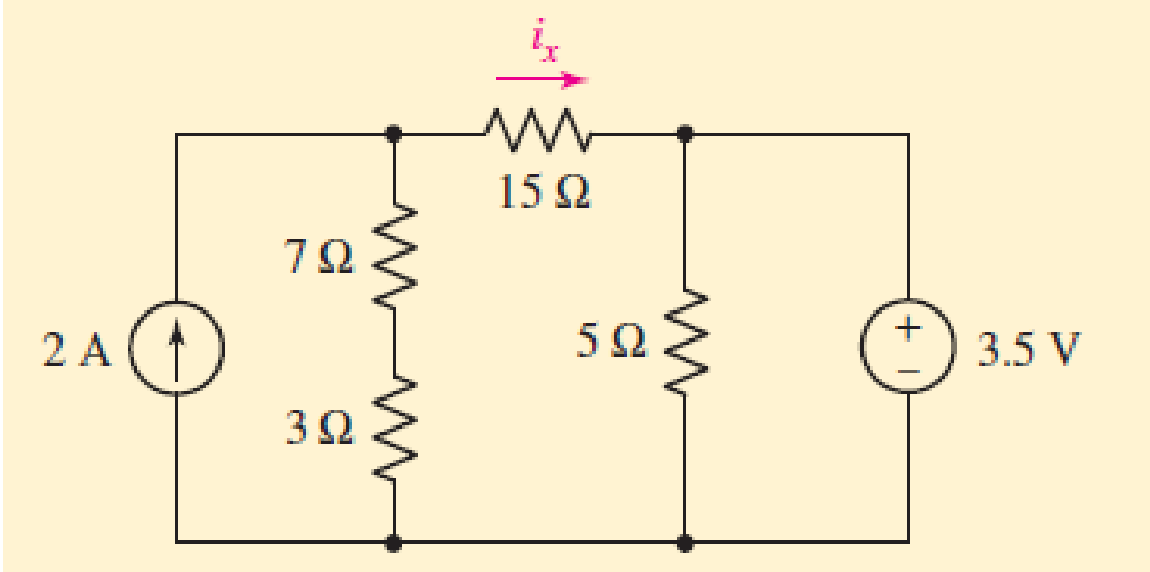
FIGURE 5.4
Expert Solution & Answer
Want to see the full answer?
Check out a sample textbook solution
Students have asked these similar questions
Q1. Consider the unity feedback control system whose open-loop
transfer function is:
G(s):
=
40(S+2)
s(s+3)(s+1)(s + 10)
ELECTRIC
Ziegler-Nichols,
By using second method of Ziegler- Nichols, calculate the PID, PI-D and
I-PD parameters and make tuning for this parameters to get accepting
response for the following system, then comp
controllers?
PARTME
then compare your results for all types
GINEARI
I need solution by hand plz
Please solve this circuit using Laplace Transform, show proper solution.
Chapter 5 Solutions
Loose Leaf for Engineering Circuit Analysis Format: Loose-leaf
Ch. 5.1 - For the circuit of Fig. 5.4, use superposition to...Ch. 5.2 - For the circuit of Fig. 5.7, use superposition to...Ch. 5.2 - For the circuit of Fig. 5.18, compute the current...Ch. 5.2 - For the circuit of Fig. 5.20, compute the voltage...Ch. 5.3 - Using repeated source transformations, determine...Ch. 5.3 - Use Thvenins theorem to find the current through...Ch. 5.3 - Determine the Thvenin and Norton equivalents of...Ch. 5.3 - Find the Thvenin equivalent for the network of...Ch. 5.3 - Find the Thvenin equivalent for the network of...Ch. 5.4 - Consider the circuit of Fig. 5.43. FIGURE 5.43...
Ch. 5.5 - Prob. 11PCh. 5 - Linear systems are so easy to work with that...Ch. 5 - Prob. 2ECh. 5 - Prob. 3ECh. 5 - (a) Employ superposition to determine the current...Ch. 5 - (a) Using superposition to consider each source...Ch. 5 - (a) Determine the individual contributions of each...Ch. 5 - (a) Determine the individual contributions of each...Ch. 5 - After studying the circuit of Fig. 5.53, change...Ch. 5 - Consider the three circuits shown in Fig. 5.54....Ch. 5 - (a) Using superposition, determine the voltage...Ch. 5 - Employ superposition principles to obtain a value...Ch. 5 - (a) Employ superposition to determine the...Ch. 5 - Perform an appropriate source transformation on...Ch. 5 - (a) For the circuit of Fig. 5.59, plot iL versus...Ch. 5 - Determine the current labeled I in the circuit of...Ch. 5 - Verify that the power absorbed by the 7 resistor...Ch. 5 - (a) Determine the current labeled i in the circuit...Ch. 5 - (a) Using repeated source transformations, reduce...Ch. 5 - Prob. 19ECh. 5 - (a) Making use of repeated source transformations,...Ch. 5 - Prob. 21ECh. 5 - (a) With the assistance of source transformations,...Ch. 5 - For the circuit in Fig. 5.67 transform all...Ch. 5 - Prob. 24ECh. 5 - (a) Referring to Fig. 5.69, determine the Thevenin...Ch. 5 - (a) With respect to the circuit depicted in Fig....Ch. 5 - (a) Obtain the Norton equivalent of the network...Ch. 5 - (a) Determine the Thevenin equivalent of the...Ch. 5 - Referring to the circuit of Fig. 5.71: (a)...Ch. 5 - Prob. 30ECh. 5 - (a) Employ Thvenins theorem to obtain a...Ch. 5 - Prob. 32ECh. 5 - Determine the Norton equivalent of the circuit...Ch. 5 - For the circuit of Fig. 5.75: (a) Employ Nortons...Ch. 5 - (a) Obtain a value for the Thvenin equivalent...Ch. 5 - Prob. 36ECh. 5 - Obtain a value for the Thvenin equivalent...Ch. 5 - With regard to the network depicted in Fig. 5.79,...Ch. 5 - Determine the Thvenin and Norton equivalents of...Ch. 5 - Determine the Norton equivalent of the circuit...Ch. 5 - Prob. 41ECh. 5 - Determine the Thvenin and Norton equivalents of...Ch. 5 - Prob. 43ECh. 5 - Prob. 44ECh. 5 - Prob. 45ECh. 5 - (a) For the simple circuit of Fig. 5.87, find the...Ch. 5 - For the circuit drawn in Fig. 5.88, (a) determine...Ch. 5 - Study the circuit of Fig. 5.89. (a) Determine the...Ch. 5 - Prob. 49ECh. 5 - Prob. 50ECh. 5 - With reference to the circuit of Fig. 5.91, (a)...Ch. 5 - Prob. 52ECh. 5 - Select a value for RL in Fig. 5.93 such that it...Ch. 5 - Determine what value of resistance would absorb...Ch. 5 - Derive the equations required to convert from a...Ch. 5 - Convert the - (or "-") connected networks in Fig....Ch. 5 - Convert the Y-(or T-) connected networks in Fig....Ch. 5 - For the network of Fig. 5.97, select a value of R...Ch. 5 - For the network of Fig. 5.98, select a value of R...Ch. 5 - Prob. 60ECh. 5 - Calculate Rin as indicated in Fig.5.100. FIGURE...Ch. 5 - Employ Y conversion techniques as appropriate to...Ch. 5 - Prob. 63ECh. 5 - (a) Use appropriate techniques to obtain both the...Ch. 5 - (a) For the network in Fig. 5.104, replace the...Ch. 5 - Prob. 66ECh. 5 - Prob. 67ECh. 5 - A 2.57 load is connected between terminals a and...Ch. 5 - A load resistor is connected across the open...Ch. 5 - A backup is required for the circuit depicted in...Ch. 5 - (a) Explain in general terms how source...Ch. 5 - The load resistor in Fig. 5.108 can safely...Ch. 5 - Prob. 74ECh. 5 - As part of a security system, a very thin 100 ...Ch. 5 - With respect to the circuit in Fig. 5.90, (a)...
Additional Engineering Textbook Solutions
Find more solutions based on key concepts
How are relationships between tables expressed in a relational database?
Modern Database Management
What types of coolant are used in vehicles?
Automotive Technology: Principles, Diagnosis, And Service (6th Edition) (halderman Automotive Series)
This optional Google account security feature sends you a message with a code that you must enter, in addition ...
SURVEY OF OPERATING SYSTEMS
A byte is made up of eight a. CPUs b. addresses c. variables d. bits
Starting Out with Java: From Control Structures through Objects (7th Edition) (What's New in Computer Science)
What is an uninitialized variable?
Starting Out with Programming Logic and Design (5th Edition) (What's New in Computer Science)
1.2 Explain the difference between geodetic and plane
surveys,
Elementary Surveying: An Introduction To Geomatics (15th Edition)
Knowledge Booster


Learn more about
Need a deep-dive on the concept behind this application? Look no further. Learn more about this topic, electrical-engineering and related others by exploring similar questions and additional content below.Similar questions
- Please show step by step solution.arrow_forwardExample 1: There is a transfer function for a second-order system given as follows. 120 G(s)= s²+12s+120 Find 5,,, T, T, T., and %OS.arrow_forward5. Please sketch a root locus manually for the following system. R(s) + E(s) C(s) k(s + 1) s² + 2s +2 Each branch in your root locus must be labeled with an arrow. Please answer the following questions. a. Is the closed-loop system stable as k is varying from 0 to co? Please find an answer to this question via root locus. b. What are finite zeros and poles? Are there infinite zeros? If so, how many?arrow_forward
- -5. Draw the connection diagram for two parallel transformers with (A-A) connected?arrow_forwardHW_#6 HW_06.pdf EE 213-01 Assignments zm Rich LTI uah.instructure.com Z (MAE 272-01) (SP25) DYNAMICS b My Questions | bartleby ✓ Download → Info Page 1 > of 2 - ZOOM + 1) (5 pts) Note have to use nodal analysis at Vp and Vn. a) Determine Vout in the following ideal op-amp circuit. The power supplies supplying power to the op-amp have voltage values of ±15 volts (Vcc = +15 Volts, -VCC = -15Volts) b) Determine the value of RĘ that makes Vo, -15 Volts. c) What value of RF makes Vo = 0 Volts? out F out = 2V 1V 25K 10K 2V 1V 30K 100K RF 12K 12K + E น out E 2) (5 pts) Find Vout in the following circuit. Perform nodal analysis at nodes VN, VP and Va 20K Va 20K 10K 10K 1 V 2 V 5K Vout 15K Note: There is no restriction on the value for Vout for this problem. 3) (5 pts) For the Thevenin equivalent circuit shown, answer the following questions: 250 Ohms a 200 V ° b a) What load resistor results in maximum power delivered to that resistor? b) What is the maximum power delivered to the resistor in…arrow_forwardSuppose the Laplace transform of a causal signal x₁ (t) is given by X₁(s) s+2 s²+1 (a) What is the Fourier transform X₁ (w) of the signal? (b) Using the Laplace transform properties, find the Laplace transform of the following signal x2(t). x2(t) = e³ x₁(t−1)-4x₁(4) Note, you do not need to simplify the expression of X2(s). However, state whether it is possible to write X2(s) as a rational fraction (i.e. ratio of polynomials) in s.arrow_forward
- Consider the following mechanical system. In the figure, y(t) denotes the displacement of the mass from its equilibrium position and u(t) denotes the force applied to the mass. k1 kz - y(t) -0000 0000 3 ► u(t) b a) Find the differential equation model of the system. b) Find the state-space model for the system. Write x, A, B, C and D clearly in your answer.arrow_forwardSee whole documentarrow_forwardC(s) a) Reduce the following system to a single transfer function G(s): R(s) G3(s) R(s) C(s) G1(s) G2(s) G4(s) b) If the input r(t) is a step signal, what will be the output C(s)? Hint: Move the block G₂(s).arrow_forward
- Consider the following electrical system. In the figure, u(t) and y(t) denote the input and output voltages, respectively. Please note that y(t) is the voltage across the resistor. с u(t) +1 y(t) R 0000 a) Find the differential equation model of the system. b) Write the transfer function H(s) = Y(s) of the system. U(s) c) If u(t) = 1 volt, what will be the steady-state output voltage?arrow_forwardQ1: A Moore model sequential network has one input (X) and two outputs (Z2 Z1). An output Z2 = 1 and Z1 =0 occurs every time the input sequence 110 is completed and An output Z2 = 0 and Z1 1 occurs every time the input sequence 010 is completed otherwise Z2 = 0 and Z1 =0. Overlap is not allowed. Use D flip-flops in your design: a) Sketch the state diagram with minimum number of states. b) Construct the state table. = c) Construct the state assigned table. d) Determine the next-state and output logic expressions. e) Sketch the logic circuit.arrow_forwardConsider the following system where two objects are separated by a thermal conductor with thermal resistance R = 1. The temperatures of the objects are denoted by T₁ (t) and T2(t) and their thermal capacities are C₁ = 1 and C2 = 2. Assume, quantities follow their respective SI units. T₁(+) C₁ = 1 12(+) C₂=2 R=1 |T,(0) = 20° -Insulator: no heat flow 5260033500 If the initial temperatures of the two objects are 20°C and 50°C respectively, what will be the steady-state values of the temperatures of these two objects? What is the impact of R in the steady-state value?arrow_forward
arrow_back_ios
SEE MORE QUESTIONS
arrow_forward_ios
Recommended textbooks for you
 Introductory Circuit Analysis (13th Edition)Electrical EngineeringISBN:9780133923605Author:Robert L. BoylestadPublisher:PEARSON
 Delmar's Standard Textbook Of ElectricityElectrical EngineeringISBN:9781337900348Author:Stephen L. HermanPublisher:Cengage Learning
 Programmable Logic ControllersElectrical EngineeringISBN:9780073373843Author:Frank D. PetruzellaPublisher:McGraw-Hill Education
 Fundamentals of Electric CircuitsElectrical EngineeringISBN:9780078028229Author:Charles K Alexander, Matthew SadikuPublisher:McGraw-Hill Education
 Electric Circuits. (11th Edition)Electrical EngineeringISBN:9780134746968Author:James W. Nilsson, Susan RiedelPublisher:PEARSON
 Engineering ElectromagneticsElectrical EngineeringISBN:9780078028151Author:Hayt, William H. (william Hart), Jr, BUCK, John A.Publisher:Mcgraw-hill Education,
Introductory Circuit Analysis (13th Edition)
Electrical Engineering
ISBN:9780133923605
Author:Robert L. Boylestad
Publisher:PEARSON
Delmar's Standard Textbook Of Electricity
Electrical Engineering
ISBN:9781337900348
Author:Stephen L. Herman
Publisher:Cengage Learning
Programmable Logic Controllers
Electrical Engineering
ISBN:9780073373843
Author:Frank D. Petruzella
Publisher:McGraw-Hill Education
Fundamentals of Electric Circuits
Electrical Engineering
ISBN:9780078028229
Author:Charles K Alexander, Matthew Sadiku
Publisher:McGraw-Hill Education
Electric Circuits. (11th Edition)
Electrical Engineering
ISBN:9780134746968
Author:James W. Nilsson, Susan Riedel
Publisher:PEARSON
Engineering Electromagnetics
Electrical Engineering
ISBN:9780078028151
Author:Hayt, William H. (william Hart), Jr, BUCK, John A.
Publisher:Mcgraw-hill Education,
Z Parameters - Impedance Parameters; Author: Electrical Engineering Authority;https://www.youtube.com/watch?v=qoD4AoNmySA;License: Standard Youtube License