
Shigley's Mechanical Engineering Design (McGraw-Hill Series in Mechanical Engineering)
10th Edition
ISBN: 9780073398204
Author: Richard G Budynas, Keith J Nisbett
Publisher: McGraw-Hill Education
expand_more
expand_more
format_list_bulleted
Videos
Textbook Question
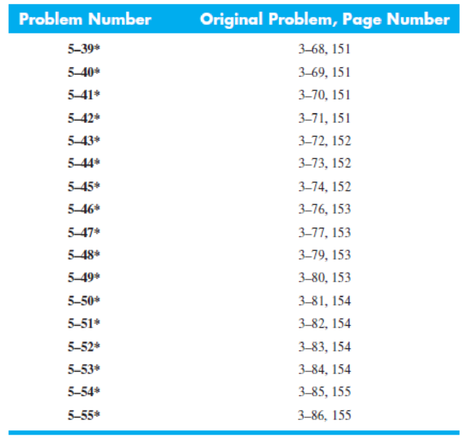
Chapter 5, Problem 54P
For the problem specified in the table, build upon the results of the original problem to determine the minimum factor of safety for yielding. Use both the maximum-shear-stress theory and the distortion-energy theory, and compare the results. The material is 1018 CD steel.
Expert Solution & Answer
Want to see the full answer?
Check out a sample textbook solution
Students have asked these similar questions
of the basket of the balloon at point A, and their other ends are staked to the ground. The hook is located in the geometric
center of the basket. The balloon and the air inside it have a combined mass of 3000 kg. You want to determine the
resultant of the tension forces in the four cables acting on the hook at point A. It is known that the magnitudes of the
tension in the cables are as follows: TAB = 207 N; TAC = 355 N; TAD = 250 N; and TAE = 486 N.
B
E
2.5 m
C
E
5.5 m
D
2.5 m
3.5 m
1.5 m
Using the information provided in the problem, express the force on the hook at point A by cable AC in rectangular component form.
The force on the hook at point A by cable AC in rectangular component form is given below.
T AC
N) i+
N) +
N) R
Water in the glass tube is at a temperature of 40°C. Plot the height of the water as a function of the tube's inner diameter D for 0.5mm≤D≤3mm. Use increments of 0.5mm. Take sigma=69.6mN/m, and theta=0° for the contact angle.
Determine the distance h that the column of mercury in the tube will be depressed when the tube is inserted into the mercury at a room temperature of 68 F. Plot this relationship of h (vertical axis) versus D for 0.5 in≤D≤0.150in. Give values for increments of ΔD=0.025in. Discuss this result
Chapter 5 Solutions
Shigley's Mechanical Engineering Design (McGraw-Hill Series in Mechanical Engineering)
Ch. 5 - A ductile hot-rolled steel bar has a minimum yield...Ch. 5 - A ductile hot-rolled steel bar has a minimum yield...Ch. 5 - A ductile hot-rolled steel bar has a minimum yield...Ch. 5 - A ductile hot-rolled steel bar has a minimum yield...Ch. 5 - A ductile hot-rolled steel bar has a minimum yield...Ch. 5 - Prob. 6PCh. 5 - 5-7 to 5-11 An AISI 1018 steel has a yield...Ch. 5 - 5-7 to 5-11 An AISI 1018 steel has a yield...Ch. 5 - 5-7 to 5-11 An AISI 1018 steel has a yield...Ch. 5 - 5-7 to 5-11 An AISI 1018 steel has a yield...
Ch. 5 - 5-7 to 5-11 An AISI 1018 steel has a yield...Ch. 5 - A ductile material has the properties Syt = 60...Ch. 5 - Prob. 13PCh. 5 - Prob. 14PCh. 5 - Prob. 15PCh. 5 - 5-14 to 5-18 An AISI 4142 steel QT at 800F...Ch. 5 - 5-14 to 5-18 An AISI 4142 steel QT at 800F...Ch. 5 - 5-14 to 5-18 An AISI 4142 steel QT at 800F...Ch. 5 - A brittle material has the properties Sut = 30...Ch. 5 - Repeat Prob. 519 by first plotting the failure...Ch. 5 - For an ASTM 30 cast iron, (a) find the factors of...Ch. 5 - For an ASTM 30 cast iron, (a) find the factors of...Ch. 5 - Prob. 23PCh. 5 - For an ASTM 30 cast iron, (a) find the factors of...Ch. 5 - 5-21 to 5-25 For an ASTM 30 cast iron, (a) find...Ch. 5 - 5-26 to 5-30 A cast aluminum 195-T6 exhibits Sut =...Ch. 5 - 5-26 to 5-30 A cast aluminum 195-T6 exhibits Sut =...Ch. 5 - 5-26 to 5-30 A cast aluminum 195-T6 exhibits Sut =...Ch. 5 - 5-26 to 5-30 A cast aluminum 195-T6 exhibits Sut =...Ch. 5 - 5-26 to 5-30 A cast aluminum 195-T6 exhibits Sut =...Ch. 5 - 5-31 to 5-35 Repeat Probs. 526 to 530 using the...Ch. 5 - 5-31 to 5-35 Repeat Probs. 526 to 530 using the...Ch. 5 - Repeat Probs. 526 to 530 using the modified-Mohr...Ch. 5 - Repeat Probs. 526 to 530 using the modified-Mohr...Ch. 5 - Repeat Probs. 526 to 530 using the modified-Mohr...Ch. 5 - This problem illustrates that the factor of safety...Ch. 5 - For the beam in Prob. 344, p. 147, determine the...Ch. 5 - A 1020 CD steel shaft is to transmit 20 hp while...Ch. 5 - For the problem specified in the table, build upon...Ch. 5 - For the problem specified in the table, build upon...Ch. 5 - 5-39 to 5-55 For the problem specified in the...Ch. 5 - Prob. 42PCh. 5 - For the problem specified in the table, build upon...Ch. 5 - For the problem specified in the table, build upon...Ch. 5 - Prob. 45PCh. 5 - 5-39 to 5-55 For the problem specified in the...Ch. 5 - Prob. 47PCh. 5 - For the problem specified in the table, build upon...Ch. 5 - For the problem specified in the table, build upon...Ch. 5 - For the problem specified in the table, build upon...Ch. 5 - For the problem specified in the table, build upon...Ch. 5 - 5-39 to 5-55 For the problem specified in the...Ch. 5 - 5-39 to 5-55 For the problem specified in the...Ch. 5 - For the problem specified in the table, build upon...Ch. 5 - For the problem specified in the table, build upon...Ch. 5 - Build upon the results of Probs. 384 and 387 to...Ch. 5 - Using F = 416 lbf, design the lever arm CD of Fig....Ch. 5 - A spherical pressure vessel is formed of 16-gauge...Ch. 5 - This problem illustrates that the strength of a...Ch. 5 - Prob. 60PCh. 5 - A cold-drawn AISI 1015 steel tube is 300 mm OD by...Ch. 5 - Prob. 62PCh. 5 - The figure shows a shaft mounted in bearings at A...Ch. 5 - By modern standards, the shaft design of Prob. 563...Ch. 5 - Build upon the results of Prob. 340, p. 146, to...Ch. 5 - For the clevis pin of Prob. 340, p. 146, redesign...Ch. 5 - A split-ring clamp-type shaft collar is shown in...Ch. 5 - Prob. 68PCh. 5 - Prob. 69PCh. 5 - Prob. 70PCh. 5 - Two steel tubes have the specifications: Inner...Ch. 5 - Repeal Prob. 5-71 for maximum shrink-fit...Ch. 5 - Prob. 73PCh. 5 - Two steel lubes are shrink-filled together where...Ch. 5 - Prob. 75PCh. 5 - Prob. 76PCh. 5 - Prob. 77PCh. 5 - Prob. 78PCh. 5 - Prob. 79PCh. 5 - Prob. 80PCh. 5 - Prob. 81PCh. 5 - For Eqs. (5-36) show that the principal stresses...Ch. 5 - Prob. 83PCh. 5 - A plate 100 mm wide, 200 mm long, and 12 mm thick...Ch. 5 - A cylinder subjected to internal pressure pi has...
Knowledge Booster


Learn more about
Need a deep-dive on the concept behind this application? Look no further. Learn more about this topic, mechanical-engineering and related others by exploring similar questions and additional content below.Similar questions
- Water is at a temperature of 30 C. Plot the height h of the water as a function of the gap w between the two glass plates for 0.4 mm ≤ w ≤ 2.4 mm. Use increments of 0.4mm. Take sigma=0.0718 N/m.arrow_forwardWhat is the reading on the vernier calipers? 7 6 0 5 10 8arrow_forwardDetermine the moments of the force about the x and the a axes. O 4 m F = {-40i +20j + 10k} N 3 m 6 m aarrow_forward
- 6. A part of the structure for a factory automation system is a beam that spans 30.0 in as shown in Figure P5-6. Loads are applied at two points, each 8.0 in from a support. The left load F₁ = 1800 lb remains constantly applied, while the right load F₂ = 1800 lb is applied and removed fre- quently as the machine cycles. Evaluate the beam at both B and C. A 8 in F₁ = 1800 lb 14 in F2 = 1800 lb 8 in D RA B C 4X2X1/4 Steel tube Beam cross section RDarrow_forward30. Repeat Problem 28, except using a shaft that is rotating and transmitting a torque of 150 N⚫m from the left bear- ing to the middle of the shaft. Also, there is a profile key- seat at the middle under the load.arrow_forward28. The shaft shown in Figure P5-28 is supported by bear- ings at each end, which have bores of 20.0 mm. Design the shaft to carry the given load if it is steady and the shaft is stationary. Make the dimension a as large as pos- sible while keeping the stress safe. Determine the required d = 20mm D = ? R = ?| 5.4 kN d=20mm Length not to scale -a = ?- +а= a = ? + -125 mm- -250 mm- FIGURE P5-28 (Problems 28, 29, and 30)arrow_forward
- 12. Compute the estimated actual endurance limit for SAE 4130 WQT 1300 steel bar with a rectangular cross sec- tion of 20.0 mm by 60 mm. It is to be machined and subjected to repeated and reversed bending stress. A reli- ability of 99% is desired.arrow_forward28. The shaft shown in Figure P5-28 is supported by bear- ings at each end, which have bores of 20.0 mm. Design the shaft to carry the given load if it is steady and the shaft is stationary. Make the dimension a as large as pos- sible while keeping the stress safe. Determine the required d = 20mm D = ? R = ?| 5.4 kN d=20mm Length not to scale -a = ?- +а= a = ? + -125 mm- -250 mm- FIGURE P5-28 (Problems 28, 29, and 30)arrow_forward2. A strut in a space frame has a rectangular cross section of 10.0 mm by 30.0 mm. It sees a load that varies from a tensile force of 20.0 kN to a compressive force of 8.0 kN.arrow_forward
- find stress at Qarrow_forwardI had a theoretical question about attitude determination. In the attached images, I gave two axis and angles. The coefficient of the axes are the same and the angles are the same. The only difference is the vector basis. Lets say there is a rotation going from n hat to b hat. Then, you introduce a intermediate rotation s hat. So, I want to know if the DCM produced from both axis and angles will be the same or not. Does the vector basis affect the numerical value of the DCM? The DCM formula only cares about the coefficient of the axis and the angle. So, they should be the same right?arrow_forward3-15. A small fixed tube is shaped in the form of a vertical helix of radius a and helix angle y, that is, the tube always makes an angle y with the horizontal. A particle of mass m slides down the tube under the action of gravity. If there is a coefficient of friction μ between the tube and the particle, what is the steady-state speed of the particle? Let y γ 30° and assume that µ < 1/√3.arrow_forward
arrow_back_ios
SEE MORE QUESTIONS
arrow_forward_ios
Recommended textbooks for you
 Elements Of ElectromagneticsMechanical EngineeringISBN:9780190698614Author:Sadiku, Matthew N. O.Publisher:Oxford University Press
 Mechanics of Materials (10th Edition)Mechanical EngineeringISBN:9780134319650Author:Russell C. HibbelerPublisher:PEARSON
 Thermodynamics: An Engineering ApproachMechanical EngineeringISBN:9781259822674Author:Yunus A. Cengel Dr., Michael A. BolesPublisher:McGraw-Hill Education
 Control Systems EngineeringMechanical EngineeringISBN:9781118170519Author:Norman S. NisePublisher:WILEY
 Mechanics of Materials (MindTap Course List)Mechanical EngineeringISBN:9781337093347Author:Barry J. Goodno, James M. GerePublisher:Cengage Learning
 Engineering Mechanics: StaticsMechanical EngineeringISBN:9781118807330Author:James L. Meriam, L. G. Kraige, J. N. BoltonPublisher:WILEY
Elements Of Electromagnetics
Mechanical Engineering
ISBN:9780190698614
Author:Sadiku, Matthew N. O.
Publisher:Oxford University Press
Mechanics of Materials (10th Edition)
Mechanical Engineering
ISBN:9780134319650
Author:Russell C. Hibbeler
Publisher:PEARSON
Thermodynamics: An Engineering Approach
Mechanical Engineering
ISBN:9781259822674
Author:Yunus A. Cengel Dr., Michael A. Boles
Publisher:McGraw-Hill Education
Control Systems Engineering
Mechanical Engineering
ISBN:9781118170519
Author:Norman S. Nise
Publisher:WILEY
Mechanics of Materials (MindTap Course List)
Mechanical Engineering
ISBN:9781337093347
Author:Barry J. Goodno, James M. Gere
Publisher:Cengage Learning
Engineering Mechanics: Statics
Mechanical Engineering
ISBN:9781118807330
Author:James L. Meriam, L. G. Kraige, J. N. Bolton
Publisher:WILEY
Understanding Failure Theories (Tresca, von Mises etc...); Author: The Efficient Engineer;https://www.youtube.com/watch?v=xkbQnBAOFEg;License: Standard youtube license