
Concept explainers
Videos
For the problem specified in the table, build upon the results of the original problem to determine the minimum factor of safety for yielding. Use both the maximum-shear-stress theory and the distortion-energy theory, and compare the results. The material is 1018 CD steel.


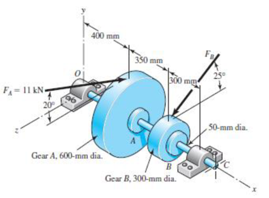
3–72* to 3–73* A gear reduction unit uses the countershaft shown in the figure. Gear A receives power from another gear with the transmitted force FA applied at the 20° pressure angle as shown. The power is transmitted through the shaft and delivered through gear B through a transmitted force FB at the pressure angle shown.
(a) Determine the force FB, assuming the shaft is running at a constant speed.
(b) Find the bearing reaction forces, assuming the bearings act as simple supports.
(c) Draw shear-force and bending-moment diagrams for the shaft. If needed, make one set for the horizontal plane and another set for the vertical plane.
(d) At the point of maximum bending moment, determine the bending stress and the torsional shear stress.
(e) At the point of maximum bending moment, determine the principal stresses and the maximum shear stress.
The factor of safety for yielding from maximum-shear-stress theory.
The factor of safety for yielding from distortion-energy theory.
Answer to Problem 44P
The factor of safety for yielding from maximum-shear-stress theory is
The factor of safety for yielding from distortion-energy theory is
Explanation of Solution
The figure below shows the free body diagram of pulley A.
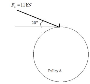
Figure-(1)
The figure below shows the free body diagram of pulley B.
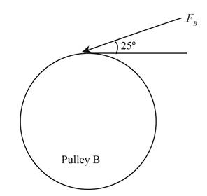
Figure-(2)
Calculate the force
Here, the force acting on pulley
Write the moment about bearing
Here, the reaction force at bearing
Write the equation to balance the forces in
Here, the reaction force at bearing
Write the moment about bearing
Here, the reaction force at bearing
Write the equation to balance the forces in
Here, the reaction force at bearing
Calculate the reaction forces at bearing
Here, the reaction force at bearing
Calculate the reaction forces at bearing
Here, the reaction force at bearing
The calculations for shear force and bending moment diagram in
Calculate the shear force at
Here, the shear force at
Calculate the shear force at
Here, the shear force at
Calculate the shear force at
Here, the shear force at
Calculate the shear force at
Here, the shear force at
Calculate the moment at
Here, the moment at
Calculate the moment at
Here, the moment at
Calculate the moment at
Here, the moment at
Write the net moment at
Here, the net moment at
Write the net moment at
Here, the net moment at
Write the torque transmitted by shaft from
Here, the torque transmitted by shaft from
Calculate the bending stress.
Here, the bending stress is
Calculate the shear stress.
Here, the shear stress is
Calculate the maximum principal stress.
Here, the maximum principal stress is
Calculate the minimum principal stress.
Here, the minimum principal stress is
Calculate the maximum shear stress.
Here, maximum shear stress is
Calculate the factor of safety from maximum-shear-stress theory.
Here, the maximum yield stress for
Calculate the factor of safety from distortion-energy theory.
Here, the Von Mises stress is
Write the expression for von Mises stress.
Substitute
Conclusion:
Convert the forces into
Substitute
Substitute
Substitute
Substitute
Substitute
Substitute
Substitute
Substitute
Substitute
Substitute
Substitute
Substitute
Substitute
Substitute
Substitute
Substitute
Substitute
Substitute
Substitute
Substitute
Substitute
Since,
The critical location is at
Substitute
Substitute
Substitute
Substitute
Substitute
Substitute
Refer to the Table A-20 “Deterministic ASTM Minimum Tensile and Yield Strengths for Some Hot-Rolled (HR) and Cold-Drawn (CD) Steels” and obtain
Substitute
Thus, the factor of safety for yielding from maximum-shear-stress theory is
Substitute
Thus, the factor of safety for yielding from distortion-energy theory is
Want to see more full solutions like this?
Chapter 5 Solutions
Shigley's Mechanical Engineering Design (McGraw-Hill Series in Mechanical Engineering)


- Determine the minimum applied force P required to move wedge A to the right. The spring is compressed a distance of 175 mm. Neglect the weight of A and B. The coefficient of static friction for all contacting surface is μs = 0.35. Neglect friction at the rollers. k = = 15 kN/m P A B 10°arrow_forwardDO NOT COPY SOLUTION- will report The differential equation of a cruise control system is provided by the following equation: Find the closed loop transfer function with respect to the reference velocity (vr) . a. Find the poles of the closed loop transfer function for different values of K. How does the poles move as you change K? b. Find the step response for different values of K and plot in MATLAB. What can you observe?arrow_forwarda box shaped barge 37m long, 6.4 m beam, floats at an even keel draught of 2.5 m in water density 1.025 kg/m3. If a mass is added and the vessel moves into water density 1000 kg/m3, determine the magnitude of this mass if the fore end and aft end draughts are 2.4m and 3.8m respectively.arrow_forward
- a ship 125m long and 17.5m beam floats in seawater of 1.025 t/m3 at a draught of 8m. the waterplane coefficient is 0.83, block coefficient 0.759 and midship section area coefficient 0.98. calculate i) prismatic coefficient ii) TPC iii) change in mean draught if the vessel moves into water of 1.016 t/m3arrow_forwardc. For the given transfer function, find tp, ts, tr, Mp . Plot the resulting step response. G(s) = 40/(s^2 + 4s + 40) handplot only, and solve for eacharrow_forwardA ship of 9000 tonne displacement floats in fresh water of 1.000 t/m3 at a draught 50 mm below the sea water line. The waterplane area is 1650 m2. Calculate the mass of cargo which must be added so that when entering seawater of 1.025 t/m3 it floats at the seawater line.arrow_forward
- A ship of 15000 tonne displacement floats at a draught of 7 metres in water of 1.000t/cub. Metre.It is required to load the maximum amount of oil to give the ship a draught of 7.0 metre in seawater ofdensity 1.025 t/cub.metre. If the waterplane area is 2150 square metre, calculate the massof oil requiredarrow_forwardA ship of 8000 tonne displacement floats in seawater of 1.025 t/m3 and has a TPC of 14. The vessel moves into fresh water of 1.000 t/m3 and loads 300 tonne of oil fuel. Calculate the change in mean draught.arrow_forwardAuto Controls DONT COPY ANSWERS - will report Perform the partial fraction expansion of the following transfer function and find the impulse response: G(s) = (s/2 + 5/3) / (s^2 + 4s + 6) G(s) =( 6s^2 + 50) / (s+3)(s^2 +4)arrow_forward
- I submitted the below question and received the answer i copied into this question as well. Im unsure if it is correct, so looking for a checkover. i am stuck on the part tan-1 (0.05) = 0.04996 radians. Just unsure where the value for the radians came from. Just need to know how they got that answer and how it is correct before moving on to the next part. If any of the below information is wrong, please feel free to give me a new answer or an entire new explanation. An Inclining experiment done on a ship thats 6500 t, a mass of 30t was moved 6.0 m transvesly causing a 30 cm deflection in a 6m pendulum, calculate the transverse meta centre height. Here is the step-by-step explanation: Given: Displacement of the ship (W) = 6500 tonnes = 6500×1000=6,500,000kg Mass moved transversely (w) = 30 tonnes=30×1000=30,000kg The transverse shift of mass (d) = 6.0 meters Pendulum length (L) = 6.0 meters Pendulum deflection (x) = 30 cm = 0.30 meters Step 1: Formula for Metacentric Height…arrow_forwardAnswer the assignment question, expert onlyarrow_forwardA 1 inch rod diameter B 3/4 inch rod diameter C 1/2 inch rod diameter D 3/8 inch rod diameterarrow_forward
 Mechanics of Materials (MindTap Course List)Mechanical EngineeringISBN:9781337093347Author:Barry J. Goodno, James M. GerePublisher:Cengage Learning