
Concept explainers
Videos
For the problem specified in the table, build upon the results of the original problem to determine the minimum factor of safety for yielding. Use both the maximum-shear-stress theory and the distortion-energy theory, and compare the results. The material is 1018 CD steel.

3–68* to 3–71*
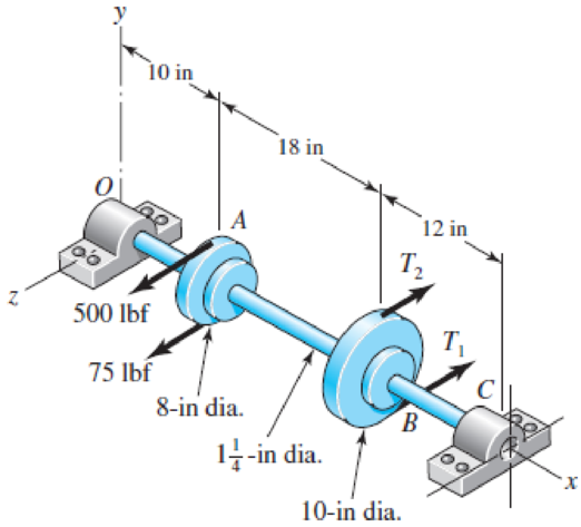
A countershaft carrying two V-belt pulleys is shown in the figure. Pulley A receives power from a motor through a belt with the belt tensions shown. The power is transmitted through the shaft and delivered to the belt on pulley B. Assume the belt tension on the loose side at B is 15 percent of the tension on the tight side.
(a) Determine the tensions in the belt on pulley B, assuming the shaft is running at a constant speed.
(b) Find the magnitudes of the bearing reaction forces, assuming the bearings act as simple supports.
(c) Draw shear-force and bending-moment diagrams for the shaft. If needed, make one set for the horizontal plane and another set for the vertical plane.
(d) At the point of maximum bending moment, determine the bending stress and the torsional shear stress.
(e) At the point of maximum bending moment, determine the principal stresses and the maximum shear stress.
Problem 3–68*
The factor of safety for yielding from maximum-shear-stress theory.
The factor of safety for yielding from distortion-energy theory.
Answer to Problem 39P
The factor of safety for yielding from maximum-shear-stress theory is
The factor of safety for yielding from distortion-energy theory is
Explanation of Solution
The Free body diagram of pulley
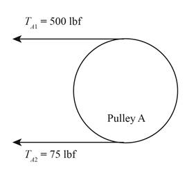
Figure-(1)
The free body diagram of pulley
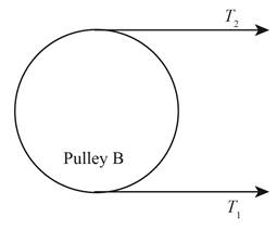
Figure-(2)
The given assumption is that the belt tension on the loose side at
Write the relationship between tension on the loose side with respect to tension on the tight side.
Here, the tension on the loose side is
Write the equation to balance the tension on the counter shaft.
Here, the tension on the tight side of pulley
Substitute
Write the tension on the loose side.
Write the magnitude of bearing reaction force at
Here, the magnitude of the bearing force at
Write the magnitude of bearing reaction force at
Here, the magnitude of bearing reaction force at
Write the shear force at
Here, the shear force at
Write the shear force at
Here, the shear force at
Write the shear force at
Here, the shear force at
Write the shear force at
Here, the shear force at
We know that, the moment at the supports of the simply supported beam is zero.
Write the moment at
Here, the moment at
Write the moment at
Here, the moment at
Write the moment at
Here, the moment at
It is clear from the shear force diagram and bending moment diagram of the shaft that the point of maximum bending moment is at
Write the torque acting at pulley
Here, the torque acting on pulley
Write the bending stress.
Here, the bending stress is
Write the shear stress.
Here, the shear stress is
Write the maximum principal stress.
Here, the maximum principal stress is
Calculate the minimum principal stress.
Here, the minimum principal stress is
Write the maximum shear stress.
Here, maximum shear stress is
Calculate the factor of safety from maximum-shear-stress theory.
Here, the maximum yield stress for
Calculate the factor of safety from distortion-energy theory.
Here, the Von Mises stress is
Write the expression for von Mises stress.
Substitute
Conclusion:
Substitute
Substitute
Substitute
Substitute
Substitute
Substitute
Substitute
Substitute
Substitute
Substitute
The shear force diagram and bending moment diagram for the shaft is as follows.
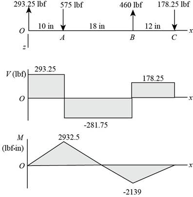
Figure-(3)
Substitute
Substitute
Substitute
Substitute
Substitute
Substitute
Refer to the Table A-20 “Deterministic ASTM Minimum Tensile and Yield Strengths for Some Hot-Rolled (HR) and Cold-Drawn (CD) Steels” to obtain the yield strength of
Substitute
Thus, the factor of safety for yielding from maximum-shear-stress theory is
Substitute
Thus, the factor of safety for yielding from distortion-energy theory is
Want to see more full solutions like this?
Chapter 5 Solutions
Shigley's Mechanical Engineering Design (McGraw-Hill Series in Mechanical Engineering)


- I have Euler parameters that describe the orientation of N relative to Q, e = -0.7071*n3, e4 = 0.7071. I have Euler parameters that describe the orientation of U relative to N, e = -1/sqrt(3)*n1, e4 = sqrt(2/3). After using euler parameter rule of successive rotations, I get euler parameters that describe the orientation of U relative to Q, e = -0.4082*n1 - 0.4082*n2 - 0.5774*n3. I need euler parameters that describe the orientation of U relative to Q in vector basis of q instead of n. How do I get that?arrow_forwardDescribe at least 4 processes in engineering where control charts are (or should be) appliedarrow_forwardDescribe at least two (2) processes where control charts are (or should be) applied.arrow_forward
- Problem 3: A cube-shaped spacecraft is in a circular Earth orbit. Let N (n,) be inertial and the spacecraft is denoted S (ŝ₁). The spacecraft is described such that ¯½º = J ŝ₁ŝ₁ + J ŝ₂§₂ + J §¸Ŝ3 Location of the spacecraft in the orbit is determined by the orbit-fixed unit vectors ê, that are oriented by the angle (Qt), where is a constant angular rate. 52 €3 3> 2t 55 Λ Из At the instant when Qt = 90°, the spacecraft S is oriented relative to the orbit such that 8₁ = 0° Space-three 1-2-3 angles 0₂ = 60° and ES = $₂ rad/s 0₁ = 135° (a) At this instant, determine the direction cosine matrix that describes the orientation of the spacecraft with respect to the inertial frame N.arrow_forwardThis problem illustrates that the factor of safety for a machine element depends on the particular point selected for analysis. Here you are to compute factors of safety, based upon the distortion-energy theory, for stress elements at A and B of the member shown in the figure. This bar is made of AISI 1006 cold-drawn steel and is loaded by the forces F = 1.100 kN, P = 8.00 kN, and T = 50.00 N-m. Given: Sy = 280 MPa. B -100 mm- 15-mm D. a) Determine the value of the axial stress at point B. b) Determine the value of the shear stress at point B. c) Determine the value of the Von Mises stress at point B. P Farrow_forwardA piston-cylinder device initially contains 0.08 m^3 of nitrogen gas at 130 kPa and 170°C. The nitrogen is expanded to a pressure of 80 kPa via isentropic expansion. Determine the final temperature and the boundary work done by the system during this process.arrow_forward
- A Carnot (ideal) heat pump is to be used to heat a house and maintain it at 22°C in winter. On a day when the average outdoor temperature remains at about 0°C, the house is estimated to lose heat at a rate of 65,000 kJ/h. If the heat pump consumes 6 kW of power while operating, determine: (a) how long the heat pump ran on that day (b) the total heating costs, assuming an average price of 11¢/kWh for electricity (c) the heating cost for the same day if an 85% efficient electric furnace is used instead of a heat pump.arrow_forwardFrom the information in the image, I needed to find the orientation of U relative to Q in vector basis q_hat. I transformed the euler angle/axis representation to euler parameters. Then I got its conjugate in order to get the euler parameter in N frame relative to Q. The problem gave the euler angle/axis representation in Q frame relative to N, so I needed to find the conjugate. Then I used the euler parameter rule of successive rotation to find the final euler parameters that describe the orientation of U relative to Q. However that orientation is in n_hat which is the intermediate frame. How do I get the final result in q_hat?arrow_forwardA proposed method of power generation involves collecting and storing solar energy in large artificial lakes a few meters deep, called solar ponds. Solar energy is absorbed by all parts of the pond, and the water temperature rises everywhere. The top part of the pond, however, loses much of the heat it absorbs to the atmosphere, and as a result, the cool surface water serves as insulation for the bottom part of the pond and helps trap the energy there. Usually, salt is planted at the bottom of the pond to prevent the rise of this hot water to the top. A heat engine that uses an organic fluid, such as alcohol, as the working fluid can be operated between the top and the bottom portions of the pond. If the water temperature is 27°C near the surface and 72°C near the bottom of the pond, determine the maximum thermal efficiency that this power plant can have. Treat the cycle as an ideal heat engine. Would a heat engine operating under these temperature conditions (27°C and 72°C) be…arrow_forward
- A standard Carnot heat engine cycle is executed in a closed system between the temperature limits of 320 and 1350 K, with air as the working fluid. The pressures before and after the isothermal compression are 150 and 300 kPa, respectively. Sketch the TS diagram for this cycle. If the net work output per cycle is 0.75 kJ, determine the efficiency of the cycle and the heat transfer to the air (working fluid) per cycle.arrow_forwardPROBLEM 10: A sleeve in the form of a circular tube of length L is Nut placed around a bolt and fitted between washers at each end. The nut is then turned until it is just snug. Use material properties as follows: For the sleeve, as = 21 x 106/°C and Es = 100 GPa Washer Bolt ·L· Sleeve Bolt head For the bolt, αB = 10 × 10-6/°C and EB = 200 GPa. 1. Calculate the temperature rise that is required to produce a compressive stress of 25 MPa in the sleeve.arrow_forwardThis problem illustrates that the factor of safety for a machine element depends on the particular point selected for analysis. Here you are to compute factors of safety, based upon the distortion-energy theory, for stress elements at A and B of the member shown in the figure. This bar is made of AISI 1006 cold-drawn steel and is loaded by the forces F = 1.100 kN, P = 8.00 kN, and T = 50.00 N·m. Given: Sy = 280 MPa. B -100 mm- 15-mm D. a) What is the value of the axial stress at point A? b)What is the value of the shear stress at point A? c)Determine the value of the Von Mises stress at point A. P Farrow_forward
 Mechanics of Materials (MindTap Course List)Mechanical EngineeringISBN:9781337093347Author:Barry J. Goodno, James M. GerePublisher:Cengage Learning