
Concept explainers
The factor of safety for yielding from distortion-energy theory.
The factor of safety for yielding from maximum-shear-stress theory.
Answer to Problem 45P
The factor of safety for yielding from distortion-energy theory is
The factor of safety for yielding from maximum-shear-stress theory is
Explanation of Solution
The figure below shows the arrangement of shafts.
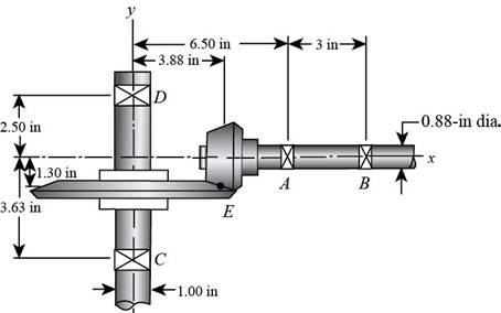
Figure (1)
The free body diagram of the arrangement of shafts is as follows.
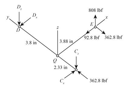
Figure (2)
Write the expression of moment at
Here, the reaction at
Write the expression of moment at
Here, the reaction at
Write the expression of moment at
Here, the reaction at
Write the expression of moment at
Write the expression of net force at
Here, the reaction at
It is clear from the free body diagram of the shaft
The calculations for shear force diagram in
Write the expression of Shear force at
Here, the shear at
Write the expression of Shear force at
Here, the shear force at
Write the expression of Shear force at
Here, the shear force at
The calculations for bending moment diagram in
We known that, the bending moment at the supports of the simply supported beam is zero.
Write the bending moment at
Here, the bending moment at
Write the expression of bending moment at
Here, the bending moment at
Write the expression of bending moment at
Here, the bending moment at
The calculations for shear force diagram in
Write the expression of Shear force at
Here, the shear at
Write the expression of Shear force at
Here, the shear force at
Write the expression of Shear force at
Here, the shear force at
The bending moment at the supports of the simply supported beam is zero.
Write the bending moment at
Here, the bending moment at
Write the expression of bending moment at
Here, the bending moment at
It is clear from the bending moment diagram that the critical stress element is located at just right of
Write the expression of maximum torque acting on the shaft
Here, the maximum torque acting on the shaft
Write the expression of maximum bending moment acting on the shaft
Here, the maximum bending moment acting on the shaft
Write the expression of torsional shear stress for critical stress element.
Here, the torsional shear stress for critical stress element is
Write the expression of bending stress for critical stress element.
Here, the bending stress for critical stress element is
Write the expression of axial stress for critical stress element.
Here, the axial stress for critical stress element is
Write the expression of maximum bending stress on the critical stress element.
Here, the maximum bending stress on the critical stress element is
Write the expression of principal stresses on the critical stress element.
Here, the principal stresses on the critical stress element are
Write the expression of maximum shear stress on the critical stress element.
Here, the maximum shear stress on the critical stress element is
Calculate the factor of safety from maximum-shear-stress theory.
Here, the maximum yield stress for
Calculate the factor of safety from distortion-energy theory.
Here, the Von Mises stress is
Write the expression for von Mises stress.
Substitute
Conclusion:
Substitute
Thus, the reaction at
Substitute
Thus, the reaction at
Substitute
Thus, the reaction at
Substitute
Thus, the reaction at
Substitute
Thus, the reaction at
Substitute
Substitute
Substitute
Substitute
Substitute
The figure below shows the shear force and bending moment diagram in
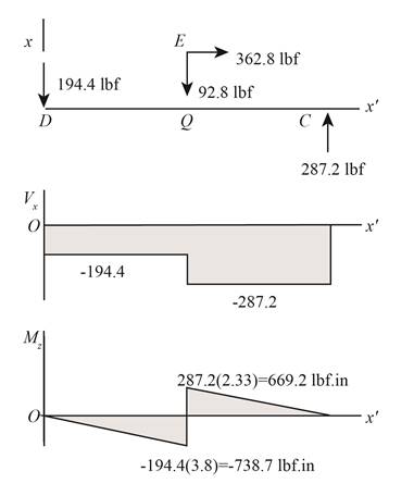
Figure (3)
Substitute
Substitute
Substitute
Substitute
The figure below shows the shear force and bending moment diagram in
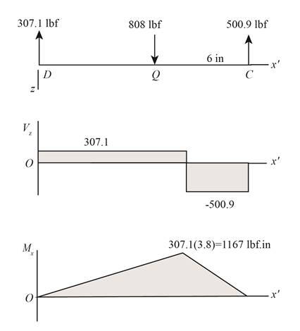
Figure (4)
Substitute
Substitute
Substitute
Thus, the torsional shear stress for critical stress element is
Substitute
Thus, the bending stress for critical stress element is
Substitute
Thus, the axial stress for critical stress element is
Substitute
Substitute
Substitute
Refer to the Table A-20 “Deterministic ASTM Minimum Tensile and Yield Strengths for Some Hot-Rolled (HR) and Cold-Drawn (CD) Steels” and obtain the yield strength as
Substitute
Thus, the factor of safety for yielding from maximum-shear-stress theory is
Substitute
Thus, the factor of safety for yielding from distortion-energy theory is
Want to see more full solutions like this?
Chapter 5 Solutions
Shigley's Mechanical Engineering Design (McGraw-Hill Series in Mechanical Engineering)


- varrow_forward13.64 The shaft shown in Sketch h transfers power between the two pulleys. The tension on the slack side (right pul- ley) is 30% of that on the tight side. The shaft rotates at 900 rpm and is supported uniformly by a radial ball bearing at points 0 and B. Select a pair of radial ball bear- ings with 99% reliability and 40,000 hr of life. Assume Eq. (13.83) can be used to account for lubricant clean- liness. All length dimensions are in millimeters. Ans. Cmin = 42,400 N.arrow_forwardA 4 inch wide, 12 inch tall cross section beam is subjected to an internal shear of 5.5 kips. What is the maximum transverse shear stress in the beam in psi if this bending is about the x axis?arrow_forward
- A Brayton cycle produces 14 MW with an inlet state of 17°C, 100 kPa, and a compression ratio of 16:1. The heat added in the combustion is 960 kJ/kg. 0.7 MW of heat transferred from the turbine to the environment. What are the highest temperature and the mass flow rate of air? Assume cold air properties.arrow_forward. A gas turbine with air enters the compressor at 300 K, 1 bar, and exits from the turbine at 750 K, 1 bar. The thermal efficiency of the cycle is 40.1% and the back work ratio (BWR) is 0.4. Find the pressure ratio of the cycle. Assume variable specific heat.arrow_forwardA regenerative gas turbine power plant is shown in Fig. below. Air enters the compressor at 1 bar, 27°C with a mass flow rate of 0.562 kg/s and is compressed to 4 bar. The isentropic efficiency of the compressor is 80%, and the regenerator effectiveness is 90%. All the power developed by the high-pressure turbine is used to run the compressor. The low-pressure turbine provides the net power output. Each turbine has an isentropic efficiency of 87% and the temperature at the inlet to the highpressure turbine is 1200 K. Assume cold air properties, determine: a. The net power output, in kW. b. The thermal efficiency of the cycle.arrow_forward
- For tixed inlet state and exit pressure, use a cold-air standard analysis to show that the pressure ratio across the two compressor stages that gives nunimum work input is:=)) k/(k-1) when Ta Ti, where Ta is the temperature of the air entering the second stage compressor and Pi is the intercooler pressure. Put the suitable assumptionsarrow_forwardDerive the equation below ah ap ax 12μ ax, +( ah ap ay 12μ ay Where P P (x, y) is the oil film pressure. 1..ah 2 axarrow_forwardCan you determine the eignevalues by hand?arrow_forward
- Monthly exam 13 2021-2022 Power plant Time: 1.5 Hrs Q1. A The gas-turbine cycle shown in Fig. is used as an automotive engine. In the first turbine, the gas expands to pressure Ps, just low enough for this turbine to drive the compressor. The gas is then expanded through the second turbine connected to the drive wheels. The data for the engine are shown in the figure, and assume that all processes are ideal. Determine the intermediate pressure Ps, the net specific work output of the engine, and the mass flow rate through the engine. Find also the air temperature entering the burner T3 and the thermal efficiency of the engine. Exhaust Air intake Φ www Regenerator www Bumer Compressor Turbine Power turbine et 150 kW Wompressor P₁ = 100 kPa T₁ = 300 K PP₁ =60 P-100 kPa T₁ = 1600 K Q2. On the basis of a cold air-standard analysis, show that the thermal efficiency of an ideal regenerative gas turbine can be expressed as 77 = 1- where - () () гp is the compressor pressure ratio, and T₁ and…arrow_forwardI need to find m in R = mD from the image given. Do you really need to know what R and D is to find R. I was thinking geometrically we can find a relationship between R and D. D = R*cos(30). Then R = mD becomes m = R/D = 1/cos(30) = 1.1547. Is that correct?arrow_forwardQ1] B/ (16 Marks) To produce a lightweight epoxy part to provide thermal insulation. The available material are hollow glass beads for which the outside diameter is 1.6 mm and the wall thickness is 0.04 mm. Determine the weight and number of beads that must be added to the epoxy to produce a 0.5 kg of composite with a density of 0.65 g/cm³. The density of the glass is 2.5 g/cm³ and that of the epoxy is 1.25 g/cm³.arrow_forward
 Mechanics of Materials (MindTap Course List)Mechanical EngineeringISBN:9781337093347Author:Barry J. Goodno, James M. GerePublisher:Cengage Learning