
Concept explainers
Videos
For the problem specified in the table, build upon the results of the original problem to determine the minimum factor of safety for yielding. Use both the maximum-shear-stress theory and the distortion-energy theory, and compare the results. The material is 1018 CD steel.


3–72* to 3–73*
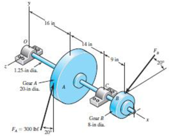
A gear reduction unit uses the countershaft shown in the figure. Gear A receives power from another gear with the transmitted force FA applied at the 20° pressure angle as shown. The power is transmitted through the shaft and delivered through gear B through a transmitted force FB at the pressure angle shown.
(a) Determine the force FB, assuming the shaft is running at a constant speed.
(b) Find the bearing reaction forces, assuming the bearings act as simple supports.
(c) Draw shear-force and bending-moment diagrams for the shaft. If needed, make one set for the horizontal plane and another set for the vertical plane.
(d) At the point of maximum bending moment, determine the bending stress and the torsional shear stress.
(e) At the point of maximum bending moment, determine the principal stresses and the maximum shear stress.
The factor of safety for yielding from distortion-energy theory.
The factor of safety for yielding from maximum-shear-stress theory.
Answer to Problem 43P
The factor of safety for yielding from distortion-energy theory is
The factor of safety for yielding from maximum-shear-stress theory is
Explanation of Solution
The figure below shows the free body diagram of pulley A.
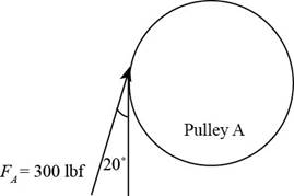
Figure (1)
The figure below shows the free body diagram of pulley B.
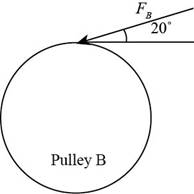
Figure (2)
Calculate the force
Here, the force acting on pulley
Write the moment about bearing
Here, the reaction force at bearing
Write the equation to balance the forces in
Here, the reaction force at bearing
Write the moment about bearing
Here, the reaction force at bearing
Write the equation to balance the forces in
Here, the reaction force at bearing
Calculate the reaction forces at bearing
Here, the reaction force at bearing
Calculate the reaction forces at bearing
Here, the reaction force at bearing
The calculations for shear force and bending moment diagram in
Calculate the shear force at
Here, the shear force at
Calculate the shear force at
Here, the shear force at
Calculate the shear force at
Here, the shear force at
Calculate the shear force at
Here, the shear force at
Calculate the moment at
Here, the moment at
Calculate the moment at
Here, the moment at
Calculate the moment at
Here, the moment at
Write the net moment at
Here, the net moment at
Write the net moment at
Here, the net moment at
Write the torque transmitted by shaft from
Here, the torque transmitted by shaft from
Calculate the bending stress.
Here, the bending stress is
Calculate the shear stress.
Here, the shear stress is
Calculate the maximum principal stress.
Here, the maximum principal stress is
Calculate the minimum principal stress.
Here, the minimum principal stress is
Calculate the maximum shear stress.
Here, maximum shear stress is
Calculate the factor of safety from maximum-shear-stress theory.
Here, the maximum yield stress for
Calculate the factor of safety from distortion-energy theory.
Here, the Von Mises stress is
Write the expression for von Mises stress.
Substitute
Conclusion:
Substitute
Thus, the force
Substitute
Substitute
Substitute
Substitute
Substitute
Substitute
Substitute
Substitute
Substitute
Substitute
Substitute
Substitute
The shear force and bending moment diagram in
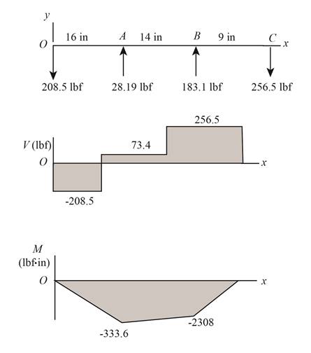
Figure-(3)
Substitute
Substitute
Substitute
Substitute
Substitute
Substitute
Thus, the shear force and bending moment diagram in
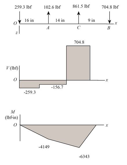
Figure-(4)
Substitute
Substitute
Since,
Substitute
Substitute
Thus, the bending stress at point of maximum bending moment is
Substitute
Substitute
Substitute
Substitute
Refer to the Table A-20 “Deterministic ASTM Minimum Tensile and Yield Strengths for Some Hot-Rolled (HR) and Cold-Drawn (CD) Steels” and obtain the yield strength as
Substitute
Thus, the factor of safety for yielding from maximum-shear-stress theory is
Substitute
Thus, the factor of safety for yielding from distortion-energy theory is
Want to see more full solutions like this?
Chapter 5 Solutions
Shigley's Mechanical Engineering Design (McGraw-Hill Series in Mechanical Engineering)


- subject: combustion please include complete solution, no rounding off, with diagram/explanation etc. In a joule cycle, intake of the compressor is 40,000 cfm at 0.3 psig and 90 deg F. The compression ratio is 6.0 and the inlet temperature at the turbine portion is 1900R while at the exit, it is 15 psi. Calculate for the back work ratio in percent.arrow_forwardsubject: combustion please include complete solution, no rounding off, with diagram/explanation etc. A gasoline engine, utilizing cold air, recorded a work of 431 BTU/lb at a maximum temperature of 3,273 K and 1112 deg F temperature at the beginning of constant volume heat addition. What is the compression ratio?arrow_forwardsubject: combustion please do step by step solution and no rounding off, complete solution with diagram/explanation if needed etc. thank you! Air enters the compressor at 101,320 Pascals, 305.15K, and leaves at a pressure of 0.808MPa. The air is heated to 990.15K in the combustion chamber. For a net output of 2,125,000 Watts, find the rate of flow of air per second.arrow_forward
- The link lengths and the value of 2 and offset for some fourbar crank-slide linkages are defined in Table 1. The linkage configuration and terminology are shown in Figure 1. For the rows assigned, find (a) all possible solutions for angle & and slider position d by vector loop method. (b) the transmission angle corresponding to angle 03. (Hint: Treat the vector R4 as virtual rocker) Show your work in details: vector loop, vector equations, solution procedure. Table 1 Row Link 2 Link 3 Offset Ө a 1.4 4 1 45° b 3 8 2 -30° C 5 20 -5 225° 03 slider axis B X offset Link 2 A R3 Link 3 R4 04 R2 02 R1 d Figure 1. Xarrow_forward4. Two links made of heat treated 6061 aluminum (Sy = 276 MPa, Sys = 160 MPa) are pinned together using a steel dowel pin (Sy = 1398 MPa, Sys = 806 MPa) as shown below. The links are to support a load P with a factor of safety of at least 2.0. Determine if the link will fail first by tearout, direct shear of the pin, bearing stress on the link, or tensile stress at section AA. (Hint: find the load P for each case and choose the case that gives the smallest load.) P 8 mm P 8 mm ¡+A 3 mm →A 10 mm Parrow_forward1. For a feature other than a sphere, circularity is where: A. The axis is a straight line B. The modifier is specified with a size dimension C. All points of the surface intersected by any plane perpendicular to an axis or spine (curved line) are equidistant from that axis or spine D. All points of the surface intersected by any plane passing through a common center are equidistant from that center 2. What type of variation is limited by a circularity toler- ance zone? A. Ovality B. Tapering C. Bending D. Warping 3. How does the Rule #1 boundary affect the application of a circularity tolerance? A. The modifier must be used. B. The feature control frame must be placed next to the size dimension. C. The circularity tolerance value must be less than the limits of size tolerance. D. Circularity cannot be applied where a Rule #1 boundary exists. 4. A circularity tolerance may use a modifier. A. Ø B. F C. M D. ℗ 5. A real-world application for a circularity tolerance is: A. Assembly (i.e.,…arrow_forward
- 3. A steel bar is pinned to a vertical support column by a 10 mm diameter hardened dowel pin, Figure 1. For P = 7500 N, find: a. the shear stress in the pin, b. the direct bearing stress on the hole in the bar, c. the minimum value of d to prevent tearout failure if the steel bar has a shear strength of 175 MPa. support column pin bar thickness of bar = 8 mm h d 150 mmarrow_forwardA press that delivers 115 strokes per minute, each stroke providing a force of 7826 N throughout a distance of 18 mm. The press efficiency is 90% and is driven by a 1749-rpm motor. Determine average torque that must be provided by the motor in the units of N-m.arrow_forward·3) find the force (P) for the figures (1) and (2) 15cm 10cm 15 h=10mm h2=6mm // Call = 90 N/2 P Agate Fig (i) Ans: 1)P=112614N 2) P=1956.5 N 25cm 25 cm الفترة أو الحجم تمر بالتي عثر اكو تورشن (ک Fig (2) h₁ = 10mm 42=6mm Cmarrow_forward
 Mechanics of Materials (MindTap Course List)Mechanical EngineeringISBN:9781337093347Author:Barry J. Goodno, James M. GerePublisher:Cengage Learning