Concept explainers
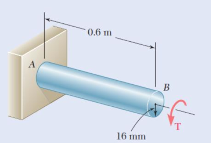
After the solid shaft of Prob. 3.116 has been loaded and unloaded as described in that problem, a torque T1 of sense opposite to the original torque T is applied to the shaft. Assuming no change in the value of ϕY, determine the angle of twist ϕ1 for which yield is initiated in this second loading and compare it with the angle ϕY for which the shaft started to yield in the original loading.
3.116 The solid shaft shown is made of a steel that is assumed to be elastoplastic with τY= 145 MPa and G = 77.2 GPa. The torque is increased in magnitude until the shaft has been twisted through 6°; the torque is then removed. Determine (a) the magnitude and location of the maximum residual shearing stress, (b) the permanent angle of twist.

Fig .P3.116
Want to see the full answer?
Check out a sample textbook solution
Chapter 3 Solutions
Mechanics of Materials, 7th Edition
- ANSWER ASAP A Solution A is best B Solution B is best C Solution C is best D Solution D is bestarrow_forwardA distillation column with a total condenser and a partial reboiler is separating ethanol andwater at 1.0 atm. Feed is 0.32 mol fraction ethanol and it enters as a saturated liquid at 100mol/s on the optimum plate. The distillate product is a saturated liquid with 80 mol% ethanol.The condenser removes 5615 kW. The bottoms product is 0.05 mol fraction ethanol. AssumeCMO is valid.(a) Find the number of equilibrium stages for this separation. [6 + PR](b) Find how much larger the actual reflux ratio, R, used is than Rmin, i.e. R/Rmin. [3]Note: the heats of vaporization of ethanol and water are λe = 38.58 and λw = 40.645 arrow_forwardA ship of 7000 tonne displacement has a waterplane areaof 1500 m2. In passing from sea water into river water of1005 kg/m3 there is an increase in draught of 10 cm. Find the Idensity of the sea water. i would like to get the above question sloved in detail. ive attached the picture of the answer from the reeds book. just not sure of all the steps theyve used and the formula in which they started with.arrow_forward
- Plunger Gauses:) - True or False "A Plunger gage can read small fluctuations in pressure such as a change in pressure of 2 psi"arrow_forwardCushioning: (Q1) A cylinder is used to clamp onto rubber tires on an assembly line. The cylinder quickly extends and clamps onto the tire and robot puts a label onto the tire. The cylinder then retracts quickly to unclamp the tire. Which of these four cylinders is best for the job? A 0 A Selection A is best B Selection B is best (C) Selection C is best D) Selection D is best B Darrow_forwardBourdon Gauges: (Q4) - True of False "A Bourdon gauge is used to measure high pressures above 500 psi"arrow_forward
- Weight of Air: If you could collect the air in a square inch column of air starting at sea level going all the way to space, how much would it weigh? Answer with one decimal. Do not write the unit.arrow_forwardPiston Area: (Q2) A cylinder applies a force of 400 pounds in extension. If the pressure in the cylinder is 39 psi what is the area of the piston in square inches? Use πon your calculator Answer with two decimals. Do not write the unit.arrow_forwardA 2D incompressible flow has velocitycomponents u= X^2 - 2y^2 and v=aX^b y^c ,where a, b, and c are numbers. Find the values of a, b, and c Find the stream functionarrow_forward
- Please can you assist with the attached question please?arrow_forward(a) Find a second-order homogeneous linear ODE for which the given functions are solutions. (b) Show linear independence by the Wronskian. (c) Solve the initial value problem. a. cos(5x), sin(5x), y(0) = 3, y'(0) = −5 b. e-2.5x cos(0.3x), e-2.5x sin(0.3x), y(0) = 3, y'(0) = -7.5arrow_forwardSolve the IVP. a. y" 16y 17e* ; = y(0) = 6, y'(0) = -2 b. (D² + 41)y = sin(t) + ½ sin(3t) + sin(t) ; y(0) = 0, y'(0) : = 35 31arrow_forward
 Elements Of ElectromagneticsMechanical EngineeringISBN:9780190698614Author:Sadiku, Matthew N. O.Publisher:Oxford University Press
 Mechanics of Materials (10th Edition)Mechanical EngineeringISBN:9780134319650Author:Russell C. HibbelerPublisher:PEARSON
 Thermodynamics: An Engineering ApproachMechanical EngineeringISBN:9781259822674Author:Yunus A. Cengel Dr., Michael A. BolesPublisher:McGraw-Hill Education
 Control Systems EngineeringMechanical EngineeringISBN:9781118170519Author:Norman S. NisePublisher:WILEY
 Mechanics of Materials (MindTap Course List)Mechanical EngineeringISBN:9781337093347Author:Barry J. Goodno, James M. GerePublisher:Cengage Learning
 Engineering Mechanics: StaticsMechanical EngineeringISBN:9781118807330Author:James L. Meriam, L. G. Kraige, J. N. BoltonPublisher:WILEY


