
Concept explainers
Videos
Ends A and D of the two solid steel shafts AB and CD are fixed, while ends B and C are connected to gears as shown. Knowing that the allowable shearing stress is 50 MPa in each shaft, determine the largest torque T that can be applied to gear B.
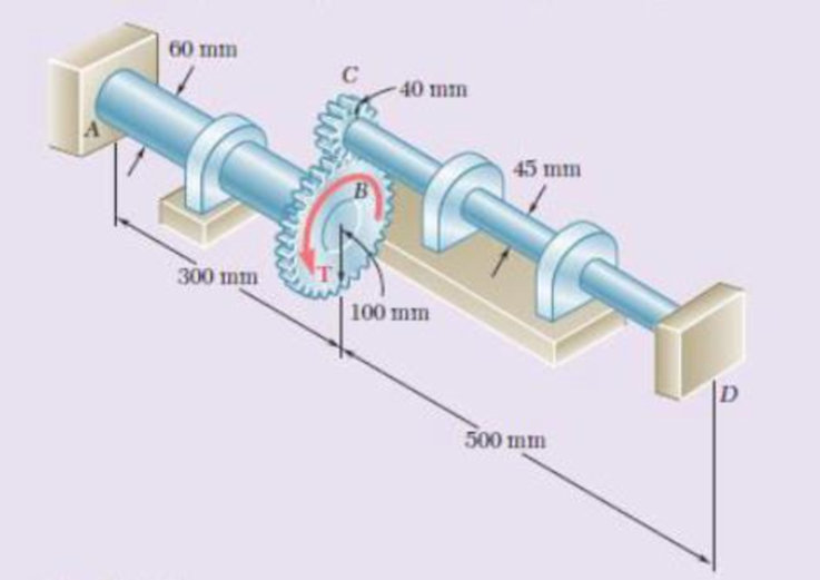
Fig. P3.157
Find the largest torque (T) that can be applied to gear B.
Answer to Problem 157RP
The largest torque (T) that can be applied to gear B is
Explanation of Solution
Given information:
The allowable shearing stress
The diameter of the shaft AB
The diameter of the shaft CD
The radius of the gear B
The radius of the gear C
The length of the shaft AB
The length of the shaft CD
Assume that clockwise direction is negative and anticlockwise direction is positive.
Calculation:
Gear B and C:
Calculate the rotation in gear B
Substitute
Show the free body diagram of the gear C as in Figure 1.
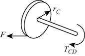
Calculate the force in the shaft CD (F) using the formula:
Show the free body diagram of the gear B as in Figure 2.
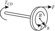
Calculate the torque produced in the shaft AB
Substitute
Substitute
Shaft AB:
Calculate the radius of the shaft AB
Substitute
Calculate the polar moment of inertia in the shaft AB
Substitute
Calculate the radius of the shaft CD
Substitute
Calculate the polar moment of inertia in the shaft CD
Substitute
Calculate the rotation about gear B
Substitute
Calculate the rotation about gear C
Substitute
Calculate the torque in CD
Substitute
Calculate the total torque (T) using the formula:
Consider the equation (2),
Substitute
Substitute
Calculate the torque in the shaft AB
Substitute
Substitute
Calculate the torque in the shaft CD
Substitute
Calculate the total torque (T):
Substitute
From the above calculated torque in the shaft AB and CD, take the lesser value.
Thus, the largest torque (T) that can be applied to gear B is
Want to see more full solutions like this?
Chapter 3 Solutions
Mechanics of Materials, 7th Edition


- correct answer only. I will upvote.arrow_forwardCorrect answer only. I will upvote.arrow_forwardI really don't know how to approach this problem i've tried approaching it with some of the torsional stress equations I know but i'm comming up with awnsers that don't make any sence can you please help me with this?arrow_forward
- I tried this problem and don't know what I did wrong or how else I could approach it can you please help me out?arrow_forwardQ3: An engine produce 750 kW power and uses gaseous C12H26 as a fuel at 25 C; 200% theoretical air is used and air enters at 500 K. The products of combustion leave at 800 K. The heat loss from the engine is 175 kW. Determine the fuel consumption for complete combustion.arrow_forwardQu 5 Determine the carburizing time necessary to achieve a carbon concentration of 0.30 wt% at a position 4 mm into an iron carbon alloy that initially contains 0.10 wt% C. The surface concentration is to be maintained at 0.90 wt% C, and the treatment is to be conducted at 1100°C. Use the data for the diffusion of carbon into y-iron: Do = 2.3 x10⁻⁵ m2/s and Qd = 148,000 J/mol. Express your answer in hours to three significant figures. show all work step by step problems formula material sciencearrow_forward
- (Read Question)arrow_forwardIn figure A, the homogeneous rod of constant cross section is attached to unyielding supports. In figure B, a homogeneous bar with a cross-sectional area of 600 mm2 is attached to rigid supports. The bar carries the axial loads P1 = 20 kN and P2 = 60 kN, as shown.1. In figure A, derive the expression that calculates the reaction R1 in terms of P, and the given dimensions.2. In figure B, calculate the reaction (kN) at A.3. In figure B, calculate the maximum axial stress (MPa) in the rod.arrow_forward(Read image)arrow_forward
- (Read Image)arrow_forwardM16x2 grade 8.8 bolts No. 25 C1- Q.2. The figure is a cross section of a grade 25 cast-iron pressure vessel. A total of N, M16x2.0 grade 8.8 bolts are to be used to resist a separating force of 160 kN. (a) Determine ks, km, and C. (b) Find the number of bolts required for a load factor of 2 where the bolts may be reused when the joint 19 mm is taken apart. (c) with the number of bolts obtained in (b), determine the realized load factor for overload, the yielding factor of safety, and the separation factor of safety. 19 mmarrow_forwardProblem4. The thin uniform disk of mass m = 1-kg and radius R = 0.1m spins about the bent shaft OG with the angular speed w2 = 20 rad/s. At the same time, the shaft rotates about the z-axis with the angular speed 001 = 10 rad/s. The angle between the bent portion of the shaft and the z-axis is ẞ = 35°. The mass of the shaft is negligible compared to the mass of the disk. a. Find the angular momentum of the disk with respect to point G, based on the axis orientation as shown. Include an MVD in your solution. b. Find the angular momentum of the disk with respect to point O, based on the axis orientation as shown. (Note: O is NOT the center of fixed-point rotation.) c. Find the kinetic energy of the assembly. z R R 002 2R x Answer: H = -0.046ĵ-0.040 kg-m²/sec Ho=-0.146-0.015 kg-m²/sec T 0.518 N-m =arrow_forward
 Elements Of ElectromagneticsMechanical EngineeringISBN:9780190698614Author:Sadiku, Matthew N. O.Publisher:Oxford University Press
 Mechanics of Materials (10th Edition)Mechanical EngineeringISBN:9780134319650Author:Russell C. HibbelerPublisher:PEARSON
 Thermodynamics: An Engineering ApproachMechanical EngineeringISBN:9781259822674Author:Yunus A. Cengel Dr., Michael A. BolesPublisher:McGraw-Hill Education
 Control Systems EngineeringMechanical EngineeringISBN:9781118170519Author:Norman S. NisePublisher:WILEY
 Mechanics of Materials (MindTap Course List)Mechanical EngineeringISBN:9781337093347Author:Barry J. Goodno, James M. GerePublisher:Cengage Learning
 Engineering Mechanics: StaticsMechanical EngineeringISBN:9781118807330Author:James L. Meriam, L. G. Kraige, J. N. BoltonPublisher:WILEY