
Videos
Solve Prob. 3.55, assuming that the shaft AB is replaced by a hollow shaft of the same outer diameter and 25-mm inner diameter.
3.55 Two solid steel shafts (G = 77.2 GPa) are connected to a coupling disk B and to fixed supports at A and C. For the loading shown, determine (a) the reaction at each support, (b) the maximum shearing stress in shaft (c) the maximum shearing stress in shaft BC.
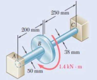
Fig. p3.55
(a)
The reaction at the supports.
Answer to Problem 56P
The reaction at the supports are
Explanation of Solution
Given information:
The modulus of rigidity of solid shafts is
Inner diameter of the shaft AB is 25 mm.
Calculation:
The outer radius of the shaft AB is
The inner radius of the shaft AB is
The polar moment of inertia of shaft AB of outer radius
The torque carried by the shaft AB
Here,
Substitute
The radius of the shaft BC is
The polar moment of inertia of shaft BC of radius
The torque carried by the shaft BC
Here,
Substitute
The value of total torque in the shaft is
The total torque
Substitute
Substitute
Therefore, the reaction at the supports are
(b)
The maximum shearing stress in the shaft AB.
Answer to Problem 56P
The maximum shearing stress in the shaft AB is
Explanation of Solution
Given information:
The modulus of rigidity of solid shafts is
Calculation:
Refer (a).
The value of torque in the shaft AB is
The polar moment of inertia of shaft AB is
The maximum shearing stress in the shaft AB
Substitute
Therefore, the maximum shearing stress in the shaft AB is
(c)
The maximum shearing stress in the shaft BC.
Answer to Problem 56P
The maximum shearing stress in the shaft BC is
Explanation of Solution
Given information:
The modulus of rigidity of solid shafts is
Calculation:
Refer (a).
The value of torque in the shaft BC is
The polar moment of inertia of shaft BC of radius
The maximum shearing stress in the shaft BC
Substitute
Therefore, the maximum shearing stress in the shaft BC is
Want to see more full solutions like this?
Chapter 3 Solutions
Mechanics of Materials, 7th Edition


- Q5:(? Design the duct system of the figure below by using the balanced pressure method. The velocity in the duct attached to the AHU must not exceed 5m/s. The pressure loss for each diffuser is equal to 10Pa. 100CFM 100CFM 100CFM ☑ ☑ 40m AHU -16m- 8m- -12m- 57m 250CFM 40m -14m- 26m 36m ☑ 250CFMarrow_forwardA mass of ideal gas in a closed piston-cylinder system expands from 427 °C and 16 bar following the process law, pv1.36 = Constant (p times v to the power of 1.36 equals to a constant). For the gas, initial : final pressure ratio is 4:1 and the initial gas volume is 0.14 m³. The specific heat of the gas at constant pressure, Cp = 0.987 kJ/kg-K and the specific gas constant, R = 0.267 kJ/kg.K. Determine the change in total internal energy in the gas during the expansion. Enter your numerical answer in the answer box below in KILO JOULES (not in Joules) but do not enter the units. (There is no expected number of decimal points or significant figures).arrow_forwardmy ID# 016948724. Please solve this problem step by steparrow_forward
- My ID# 016948724 please find the forces for Fx=0: fy=0: fz=0: please help me to solve this problem step by steparrow_forwardMy ID# 016948724 please solve the proble step by step find the forces fx=o: fy=0; fz=0; and find shear moment and the bending moment diagran please draw the diagram for the shear and bending momentarrow_forwardMy ID#016948724. Please help me to find the moment of inertia lx ly are a please show to solve step by stepsarrow_forward
- My ID# 016948724arrow_forwardPlease do not use any AI tools to solve this question. I need a fully manual, step-by-step solution with clear explanations, as if it were done by a human tutor. No AI-generated responses, please.arrow_forwardPlease do not use any AI tools to solve this question. I need a fully manual, step-by-step solution with clear explanations, as if it were done by a human tutor. No AI-generated responses, please.arrow_forward
 International Edition---engineering Mechanics: St...Mechanical EngineeringISBN:9781305501607Author:Andrew Pytel And Jaan KiusalaasPublisher:CENGAGE L
 Mechanics of Materials (MindTap Course List)Mechanical EngineeringISBN:9781337093347Author:Barry J. Goodno, James M. GerePublisher:Cengage Learning
 Principles of Heat Transfer (Activate Learning wi...Mechanical EngineeringISBN:9781305387102Author:Kreith, Frank; Manglik, Raj M.Publisher:Cengage Learning