
Mechanics of Materials, 7th Edition
7th Edition
ISBN: 9780073398235
Author: Ferdinand P. Beer, E. Russell Johnston Jr., John T. DeWolf, David F. Mazurek
Publisher: McGraw-Hill Education
expand_more
expand_more
format_list_bulleted
Concept explainers
Videos
Textbook Question
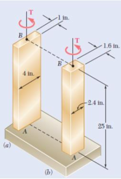
Chapter 3.10, Problem 126P
Each of the two brass bars shown is subjected to a torque of magnitude T = 12.5 kip·in. Knowing that G = 5.6 × 10⁶ psi, determine for each bar the maximum shearing stress and the angle of twist at B.
Expert Solution & Answer
Want to see the full answer?
Check out a sample textbook solution
Students have asked these similar questions
M16x2 grade 8.8 bolts No. 25 C1-
Q.2. The figure is a cross section of a grade 25 cast-iron pressure vessel. A
total of N, M16x2.0 grade 8.8 bolts are to be used to resist a separating
force of 160 kN. (a) Determine ks, km, and C. (b) Find the number of bolts
required for a load factor of 2 where the bolts may be reused when the joint 19 mm
is taken apart. (c) with the number of bolts obtained in (b), determine the
realized load factor for overload, the yielding factor of safety, and the
separation factor of safety.
19 mm
Problem4.
The thin uniform disk of mass m = 1-kg and radius R = 0.1m spins about the bent shaft OG with
the angular speed w2 = 20 rad/s. At the same time, the shaft rotates about the z-axis with the angular
speed 001 = 10 rad/s. The angle between the bent portion of the shaft and the z-axis is ẞ = 35°. The
mass of the shaft is negligible compared to the mass of the disk.
a. Find the angular momentum of the disk with respect to point G, based on the axis
orientation as shown. Include an MVD in your solution.
b. Find the angular momentum of the disk with respect to point O, based on the axis
orientation as shown. (Note: O is NOT the center of fixed-point rotation.)
c. Find the kinetic energy of the assembly.
z
R
R
002
2R
x
Answer: H = -0.046ĵ-0.040 kg-m²/sec
Ho=-0.146-0.015 kg-m²/sec
T 0.518 N-m
=
Problem 3.
The assembly shown consists of a solid sphere of mass m and the uniform slender rod of the same
mass, both of which are welded to the shaft. The assembly is rotating with angular velocity w at a
particular moment. Find the angular momentum with respect to point O, in terms of the axes
shown.
Answer: Ñ。 = ½mc²wcosßsinßĵ + (}{mr²w + 2mb²w + ½ mc²wcos²ß) k
3
m
r
b
2
C
لا
m
Chapter 3 Solutions
Mechanics of Materials, 7th Edition
Ch. 3.1 - Determine the torque T that causes a maximum...Ch. 3.1 - For the cylindrical shaft shown, determine the...Ch. 3.1 - (a) Determine the torque T that causes a maximum...Ch. 3.1 - (a) Determine the maximum shearing stress caused...Ch. 3.1 - (a) For the 3-in.-diameter solid cylinder and...Ch. 3.1 - Fig. P3.6 3.6 A torque T=3 kN m is applied to the...Ch. 3.1 - The solid spindle AB is made of a steel with an...Ch. 3.1 - The solid spindle AB has a diameter ds = 1.5 in....Ch. 3.1 - Fig. P3.9 and P3.10 3.10 The shafts of the pulley...Ch. 3.1 - Knowing that each of the shafts AB, BC, and CD...
Ch. 3.1 - Fig. P3.11 and P3.12 3.12 Knowing that an...Ch. 3.1 - Under normal operating conditions, the electric...Ch. 3.1 - In order to reduce the total mass of the assembly...Ch. 3.1 - The allowable shearing stress is 15 ksi in the...Ch. 3.1 - The allowable shearing stress is 15 ksi in the...Ch. 3.1 - The solid shaft shown is formed of a brass for...Ch. 3.1 - Solve Prob. 3.17 assuming that the direction of Tc...Ch. 3.1 - The solid rod AB has a diameter dAB= 60 mm and is...Ch. 3.1 - Fig. P3.19 and P3.20 3.20 The solid rod AB has a...Ch. 3.1 - A torque of magnitude T = 1000 N m is applied at D...Ch. 3.1 - Fig. P3.21 and P3.22 3.22 A torque of magnitude T...Ch. 3.1 - Under normal operating conditions a motor exerts a...Ch. 3.1 - Fig P3.23 and P3.24 3.24 Under normal operating...Ch. 3.1 - Prob. 25PCh. 3.1 - Fig. P3.25 and P3.26 3.26 The two solid shafts are...Ch. 3.1 - For the gear train shown, the diameters of the...Ch. 3.1 - Fig. P3.27 and P3.28 3.28 A torque T = 900 N m is...Ch. 3.1 - Fig. P3.29 3.29 While the exact distribution of...Ch. 3.1 - Fig. P3.30 3.30 (a) For a given allowable shearing...Ch. 3.3 - Determine the largest allowable diameter of a...Ch. 3.3 - The ship at A has just started to drill for oil on...Ch. 3.3 - (a) For the solid steel shaft shown, determine the...Ch. 3.3 - (a) For the aluminum pipe shown (G = 27 GPa),...Ch. 3.3 - The electric motor exerts a 500 N m-torque on the...Ch. 3.3 - The torques shown are exerted on pulleys and B....Ch. 3.3 - The aluminum rod BC (G = 26 GPa) is bonded to the...Ch. 3.3 - The aluminum rod AB (G = 27 GPa) is bonded to the...Ch. 3.3 - The solid spindle AB has a diameter ds = 1.75 in....Ch. 3.3 - Fig. p3.39 and p3.40 3.40 The solid spindle AB has...Ch. 3.3 - Two shafts, each of 78in. diameter, are connected...Ch. 3.3 - Two solid steel shafts each of 30-mm diameter, are...Ch. 3.3 - A coder F, used to record in digital form the...Ch. 3.3 - Fig. p3.43 3.44 For the gear train described in...Ch. 3.3 - The design specifications of a 1.2-m-long solid...Ch. 3.3 - 3.46 and 3.47 The solid cylindrical rod BC of...Ch. 3.3 - 3.46 and 3.47 The solid cylindrical rod BC of...Ch. 3.3 - The design of the gear-and-shaft system shown...Ch. 3.3 - The electric motor exerts a torque of 900 Nm on...Ch. 3.3 - A hole is punched at A in a plastic sheet by...Ch. 3.3 - The solid cylinders AB and BC are bonded together...Ch. 3.3 - Solve Prob. 3.51, assuming that cylinder AB is...Ch. 3.3 - The composite shaft shown consists of a...Ch. 3.3 - Fig. p3.53 and p3.54 3.54 The composite shaft...Ch. 3.3 - Two solid steel shafts (G = 77.2 GPa) are...Ch. 3.3 - Solve Prob. 3.55, assuming that the shaft AB is...Ch. 3.3 - 3.57 and 3.58 Two solid steel shafts are fitted...Ch. 3.3 - 3.57 and 3.58 Two solid steel shafts are fitted...Ch. 3.3 - The steel jacket CD has been attached to the...Ch. 3.3 - A torque T is applied as shown to a solid tapered...Ch. 3.3 - Prob. 61PCh. 3.3 - A solid shaft and a hollow shaft are made of the...Ch. 3.3 - An annular plate of thickness t and modulus G is...Ch. 3.5 - Determine the maximum shearing stress in a solid...Ch. 3.5 - Determine the maximum shearing stress in a solid...Ch. 3.5 - Using an allowable shearing stress of 4.5 ksi,...Ch. 3.5 - Using an allowable shearing stress of 50 MPa,...Ch. 3.5 - While a steel shaft of the cross section shown...Ch. 3.5 - Determine the required thickness of the 50-mm...Ch. 3.5 - A steel drive shaft is 6 ft long and its outer and...Ch. 3.5 - The hollow steel shaft shown (G = 77.2 GPa, all =...Ch. 3.5 - A steel pipe of 3.5-in. outer diameter is to be...Ch. 3.5 - 3.73 The design of a machine element calls for a...Ch. 3.5 - Three shafts and four gears are used to form a...Ch. 3.5 - Three shafts and four gears are used to form a...Ch. 3.5 - The two solid shafts and gears shown are used to...Ch. 3.5 - Fig. P3.76 and P3.77 3.77 The two solid shafts and...Ch. 3.5 - The shaft-disk-belt arrangement shown is used to...Ch. 3.5 - A 5-ft-long solid steel shaft of 0.875-in....Ch. 3.5 - A 2.5-m-long steel shaft of 30-mm diameter rotates...Ch. 3.5 - The design specifications of a 1.2-m-long solid...Ch. 3.5 - A 1.5-m-long tubular steel shaft (G = 77.2 GPa) of...Ch. 3.5 - Fig. P3.82 and P3.83 3.83 A 1.5-m-long tubular...Ch. 3.5 - The stepped shaft shown must transmit 40 kW at a...Ch. 3.5 - The stepped shaft shown rotates at 450 rpm....Ch. 3.5 - Knowing that the stepped shaft shown transmits a...Ch. 3.5 - The stepped shaft shown must rotate at a frequency...Ch. 3.5 - Fig. P3.87 and P3.88 3.88 The stepped shaft shown...Ch. 3.5 - A torque of magnitude T = 200 lbin. is applied to...Ch. 3.5 - Fig. P3.89, P3.90 and P3.91 3.90 In the stepped...Ch. 3.5 - In the stepped shaft shown, which has a full...Ch. 3.8 - The solid circular shaft shown is made of a steel...Ch. 3.8 - Prob. 93PCh. 3.8 - Prob. 94PCh. 3.8 - Prob. 95PCh. 3.8 - Fig. P3.95 and P3.96 3.96 The solid shaft shown is...Ch. 3.8 - It is observed that a straightened paper clip can...Ch. 3.8 - The solid shaft shown is made of a mild steel that...Ch. 3.8 - Prob. 99PCh. 3.8 - Prob. 100PCh. 3.8 - Prob. 101PCh. 3.8 - Prob. 102PCh. 3.8 - Prob. 103PCh. 3.8 - Prob. 104PCh. 3.8 - A solid circular rod is made of a material that is...Ch. 3.8 - Prob. 106PCh. 3.8 - Prob. 107PCh. 3.8 - Prob. 108PCh. 3.8 - Prob. 109PCh. 3.8 - Prob. 110PCh. 3.8 - Prob. 111PCh. 3.8 - A 50-mm diameter cylinder is made of a brass for...Ch. 3.8 - Prob. 113PCh. 3.8 - The solid circular drill rod AB is made of a steel...Ch. 3.8 - Prob. 115PCh. 3.8 - Prob. 116PCh. 3.8 - After the solid shaft of Prob. 3.116 has been...Ch. 3.8 - The hollow shaft shown is made of a steel that is...Ch. 3.8 - Prob. 119PCh. 3.8 - Prob. 120PCh. 3.10 - Determine the smallest allowable square cross...Ch. 3.10 - Prob. 122PCh. 3.10 - Using all = 70 MPa and G = 27 GPa, determine for...Ch. 3.10 - Prob. 124PCh. 3.10 - Determine the largest torque T that can be applied...Ch. 3.10 - Each of the two brass bars shown is subjected to a...Ch. 3.10 - Prob. 127PCh. 3.10 - Prob. 128PCh. 3.10 - Prob. 129PCh. 3.10 - Shafts A and B are made of the same material and...Ch. 3.10 - Prob. 131PCh. 3.10 - Shafts A and B are made of the same material and...Ch. 3.10 - Prob. 133PCh. 3.10 - Prob. 134PCh. 3.10 - Prob. 135PCh. 3.10 - A 36-kipin. torque is applied to a 10-ft-long...Ch. 3.10 - A 4-m-long steel member has a W310 60 cross...Ch. 3.10 - Prob. 138PCh. 3.10 - A 5-kipft torque is applied to a hollow aluminum...Ch. 3.10 - A torque T = 750 kNm is applied to the hollow...Ch. 3.10 - A 750-Nm torque is applied to a hollow shaft...Ch. 3.10 - 3.142 and 3.143 A hollow member having the cross...Ch. 3.10 - A hollow member having the cross section shown is...Ch. 3.10 - A 90-Nm torque is applied to a hollow shaft having...Ch. 3.10 - 3.145 and 3.146 A hollow member having the cross...Ch. 3.10 - 3.145 and 3.146 A hollow member having the cross...Ch. 3.10 - A cooling tube having the cross section shown is...Ch. 3.10 - A hollow cylindrical shaft was designed to have a...Ch. 3.10 - Equal torques are applied to thin-walled tubes of...Ch. 3.10 - A hollow cylindrical shaft of length L, mean...Ch. 3 - A steel pipe of 12-in. outer diameter is...Ch. 3 - A torque of magnitude T = 120 Nm is applied to...Ch. 3 - Fig. P3.152 3.153 Two solid shafts are connected...Ch. 3 - Prob. 154RPCh. 3 - Prob. 155RPCh. 3 - A torque of magnitude T = 4 kNm is applied at end...Ch. 3 - Ends A and D of the two solid steel shafts AB and...Ch. 3 - As the hollow steel shaft shown rotates at 180...Ch. 3 - Prob. 159RPCh. 3 - Prob. 160RPCh. 3 - Prob. 161RPCh. 3 - The shaft AB is made of a material that is...
Knowledge Booster


Learn more about
Need a deep-dive on the concept behind this application? Look no further. Learn more about this topic, mechanical-engineering and related others by exploring similar questions and additional content below.Similar questions
- I have Euler parameters that describe the orientation of N relative to Q, e = -0.7071*n3, e4 = 0.7071. I have Euler parameters that describe the orientation of U relative to N, e = -1/sqrt(3)*n1, e4 = sqrt(2/3). After using euler parameter rule of successive rotations, I get euler parameters that describe the orientation of U relative to Q, e = -0.4082*n1 - 0.4082*n2 - 0.5774*n3. I need euler parameters that describe the orientation of U relative to Q in vector basis of q instead of n. How do I get that?arrow_forwardDescribe at least 4 processes in engineering where control charts are (or should be) appliedarrow_forwardDescribe at least two (2) processes where control charts are (or should be) applied.arrow_forward
- Problem 3: A cube-shaped spacecraft is in a circular Earth orbit. Let N (n,) be inertial and the spacecraft is denoted S (ŝ₁). The spacecraft is described such that ¯½º = J ŝ₁ŝ₁ + J ŝ₂§₂ + J §¸Ŝ3 Location of the spacecraft in the orbit is determined by the orbit-fixed unit vectors ê, that are oriented by the angle (Qt), where is a constant angular rate. 52 €3 3> 2t 55 Λ Из At the instant when Qt = 90°, the spacecraft S is oriented relative to the orbit such that 8₁ = 0° Space-three 1-2-3 angles 0₂ = 60° and ES = $₂ rad/s 0₁ = 135° (a) At this instant, determine the direction cosine matrix that describes the orientation of the spacecraft with respect to the inertial frame N.arrow_forwardThis problem illustrates that the factor of safety for a machine element depends on the particular point selected for analysis. Here you are to compute factors of safety, based upon the distortion-energy theory, for stress elements at A and B of the member shown in the figure. This bar is made of AISI 1006 cold-drawn steel and is loaded by the forces F = 1.100 kN, P = 8.00 kN, and T = 50.00 N-m. Given: Sy = 280 MPa. B -100 mm- 15-mm D. a) Determine the value of the axial stress at point B. b) Determine the value of the shear stress at point B. c) Determine the value of the Von Mises stress at point B. P Farrow_forwardA piston-cylinder device initially contains 0.08 m^3 of nitrogen gas at 130 kPa and 170°C. The nitrogen is expanded to a pressure of 80 kPa via isentropic expansion. Determine the final temperature and the boundary work done by the system during this process.arrow_forward
- A Carnot (ideal) heat pump is to be used to heat a house and maintain it at 22°C in winter. On a day when the average outdoor temperature remains at about 0°C, the house is estimated to lose heat at a rate of 65,000 kJ/h. If the heat pump consumes 6 kW of power while operating, determine: (a) how long the heat pump ran on that day (b) the total heating costs, assuming an average price of 11¢/kWh for electricity (c) the heating cost for the same day if an 85% efficient electric furnace is used instead of a heat pump.arrow_forwardFrom the information in the image, I needed to find the orientation of U relative to Q in vector basis q_hat. I transformed the euler angle/axis representation to euler parameters. Then I got its conjugate in order to get the euler parameter in N frame relative to Q. The problem gave the euler angle/axis representation in Q frame relative to N, so I needed to find the conjugate. Then I used the euler parameter rule of successive rotation to find the final euler parameters that describe the orientation of U relative to Q. However that orientation is in n_hat which is the intermediate frame. How do I get the final result in q_hat?arrow_forwardA proposed method of power generation involves collecting and storing solar energy in large artificial lakes a few meters deep, called solar ponds. Solar energy is absorbed by all parts of the pond, and the water temperature rises everywhere. The top part of the pond, however, loses much of the heat it absorbs to the atmosphere, and as a result, the cool surface water serves as insulation for the bottom part of the pond and helps trap the energy there. Usually, salt is planted at the bottom of the pond to prevent the rise of this hot water to the top. A heat engine that uses an organic fluid, such as alcohol, as the working fluid can be operated between the top and the bottom portions of the pond. If the water temperature is 27°C near the surface and 72°C near the bottom of the pond, determine the maximum thermal efficiency that this power plant can have. Treat the cycle as an ideal heat engine. Would a heat engine operating under these temperature conditions (27°C and 72°C) be…arrow_forward
arrow_back_ios
SEE MORE QUESTIONS
arrow_forward_ios
Recommended textbooks for you
 Elements Of ElectromagneticsMechanical EngineeringISBN:9780190698614Author:Sadiku, Matthew N. O.Publisher:Oxford University Press
 Mechanics of Materials (10th Edition)Mechanical EngineeringISBN:9780134319650Author:Russell C. HibbelerPublisher:PEARSON
 Thermodynamics: An Engineering ApproachMechanical EngineeringISBN:9781259822674Author:Yunus A. Cengel Dr., Michael A. BolesPublisher:McGraw-Hill Education
 Control Systems EngineeringMechanical EngineeringISBN:9781118170519Author:Norman S. NisePublisher:WILEY
 Mechanics of Materials (MindTap Course List)Mechanical EngineeringISBN:9781337093347Author:Barry J. Goodno, James M. GerePublisher:Cengage Learning
 Engineering Mechanics: StaticsMechanical EngineeringISBN:9781118807330Author:James L. Meriam, L. G. Kraige, J. N. BoltonPublisher:WILEY
Elements Of Electromagnetics
Mechanical Engineering
ISBN:9780190698614
Author:Sadiku, Matthew N. O.
Publisher:Oxford University Press
Mechanics of Materials (10th Edition)
Mechanical Engineering
ISBN:9780134319650
Author:Russell C. Hibbeler
Publisher:PEARSON
Thermodynamics: An Engineering Approach
Mechanical Engineering
ISBN:9781259822674
Author:Yunus A. Cengel Dr., Michael A. Boles
Publisher:McGraw-Hill Education
Control Systems Engineering
Mechanical Engineering
ISBN:9781118170519
Author:Norman S. Nise
Publisher:WILEY
Mechanics of Materials (MindTap Course List)
Mechanical Engineering
ISBN:9781337093347
Author:Barry J. Goodno, James M. Gere
Publisher:Cengage Learning
Engineering Mechanics: Statics
Mechanical Engineering
ISBN:9781118807330
Author:James L. Meriam, L. G. Kraige, J. N. Bolton
Publisher:WILEY
Everything About COMBINED LOADING in 10 Minutes! Mechanics of Materials; Author: Less Boring Lectures;https://www.youtube.com/watch?v=N-PlI900hSg;License: Standard youtube license