
Mechanics of Materials (MindTap Course List)
9th Edition
ISBN: 9781337093347
Author: Barry J. Goodno, James M. Gere
Publisher: Cengage Learning
expand_more
expand_more
format_list_bulleted
Concept explainers
Videos
Textbook Question
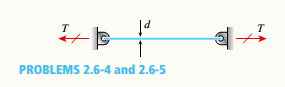
Chapter 2, Problem 2.6.4P
A brass wire of diameter d = 2.42 mm is stretched tightly between rigid supports so that the tensile force is T = 98 N (see figure). The coefficient of thermal expansion for the wire is 19.5 × 10⁻⁶/°C. and the modulus of elasticity is E = 110 GPa.
(a) What is the maximum permissible temperature drop AT if the allowable shear stress in the wire is 60 MPa?
(b) At what temperature change does the wire go slack?
Expert Solution & Answer

Trending nowThis is a popular solution!

Students have asked these similar questions
The 150-lb skater passes point A with a speed of 6 ft/s.
(Figure 1)
Determine his speed when he reaches point B. Neglect friction.
Determine the normal force exerted on him by the track at this point.
25 ft
B
= 4x
A
20 ft
x
A virtual experiment is designed to determine the effect of friction on the timing and speed
of packages being delivered to a conveyor belt and the normal force applied to the tube.
A package is held and then let go at the edge of a circular shaped tube of radius R = 5m.
The particle at the bottom will transfer to the conveyor belt, as shown below.
Run the simulations for μ = 0, 0.1, 0.2, 0.3, 0.4, 0.5, 0.6 and determine the time and speed at
which the package is delivered to the conveyor belt. In addition, determine the maximum
normal force and its location along the path as measured by angle 0.
Submit in hardcopy form:
(0) Free Body Diagram, equations underneath, derivations
(a) Your MATLAB mfile
(b) A table listing the values in 5 columns:
μ, T (time of transfer), V (speed of transfer), 0 (angle of max N), Nmax (max N)
(c) Based on your results, explain in one sentence what you think will happen to the
package if the friction is increased even further, e.g. μ = 0.8.
NOTE: The ODE is…
Patm = 1 bar
Piston
m = 50 kg
5 g of Air
T₁ = 600 K
P₁ = 3 bar
Stops
A 9.75 x 10⁻³ m²
FIGURE P3.88
Chapter 2 Solutions
Mechanics of Materials (MindTap Course List)
Ch. 2 - A 10-ft rigid bar AB is supported with a vertical...Ch. 2 - Rigid bar ABC is supported with a pin at A and an...Ch. 2 - The L-shaped arm ABCD shown in the figure lies in...Ch. 2 - A steel cable with a nominal diameter of 25 mm...Ch. 2 - A steel wire- and an aluminum allay wire have...Ch. 2 - By what distance h does the cage shown in the...Ch. 2 - Rigid bar ACB is supported by an elastic circular...Ch. 2 - A plastic cylinder is held snugly between a rigid...Ch. 2 - A safety valve on the top of a tank containing...Ch. 2 - The device shown in the figure consists of a...
Ch. 2 - A small lab scale has a rigid L-shaped frame ABC...Ch. 2 - A small lab scale has a rigid L-shaped frame ABC...Ch. 2 - Two rigid bars are connected to each other by two...Ch. 2 - The three-bar truss ABC shown in the figure part a...Ch. 2 - An aluminum wire having a diameter d = 1/10 in....Ch. 2 - A uniform bar AB of weight W = 25 N is supported...Ch. 2 - A hollow, circular, cast-iron pipe (Ec =12,000...Ch. 2 - The horizon Lai rigid beam A BCD is supported by...Ch. 2 - Two pipe columns (AB, FC) are pin-connected to a...Ch. 2 - A framework ABC consists of two rigid bars AB and...Ch. 2 - Solve the preceding problem for the following...Ch. 2 - The length of the end segments of the bar (see...Ch. 2 - A long, rectangular copper bar under a tensile...Ch. 2 - An aluminum bar AD (see figure) has a...Ch. 2 - A vertical bar consists of three prismatic...Ch. 2 - A vertical bar is loaded with axial loads at...Ch. 2 - Repeat Problem 2.3-4, but now include the weight...Ch. 2 - -7 Repeat Problem 2.3-5, but n include the weight...Ch. 2 - A rectangular bar of length L has a slot in the...Ch. 2 - Solve the preceding problem if the axial stress in...Ch. 2 - A two-story building has steel columns AB in the...Ch. 2 - A steel bar is 8.0 Ft long and has a circular...Ch. 2 - A bar ABC of length L consists of two parts of...Ch. 2 - A woodpile, driven into the earth, supports a load...Ch. 2 - Consider the copper lubes joined in the strength...Ch. 2 - The nonprismalic cantilever circular bar shown has...Ch. 2 - *16 A prismatic bar AB of length L,...Ch. 2 - A flat bar of rectangular cross section, length L,...Ch. 2 - A flat brass bar has length L, constant thickness...Ch. 2 - Repeat Problem 2.3-18, but assume that the bar is...Ch. 2 - Repeat Problem 2.3-18, but assume that the bar is...Ch. 2 - A slightly tapered bar AB of solid circular crass...Ch. 2 - A circular aluminum alloy bar of length L = 1.8 m...Ch. 2 - A long, slender bar in the shape of a right...Ch. 2 - A post AB supporting equipment in a laboratory is...Ch. 2 - The main cables of a suspension bridge (see figure...Ch. 2 - A uniformly tapered lube AB of circular cross...Ch. 2 - A vertical steel bar ABC is pin-supported at its...Ch. 2 - A T-frame structure is torn posed of a prismatic...Ch. 2 - A T-frame structure is composed of prismatic beam...Ch. 2 - Repeat Problem 2.3-29 if vertical load P at D is...Ch. 2 - A bar ABC revolves in a horizontal plane about a...Ch. 2 - The assembly shown in the figure consists of a...Ch. 2 - A cylindrical assembly consisting of a brass core...Ch. 2 - A steel bar with a uniform cross section, is fixed...Ch. 2 - A horizontal rigid bar ABC is pinned at end A and...Ch. 2 - A solid circular steel cylinder S is encased in a...Ch. 2 - Three prismatic bars, two of material A and one of...Ch. 2 - A circular bar ACB of a diameter d having a...Ch. 2 - Bar ABC is fixed at both ends (see figure) and has...Ch. 2 - Repeat Problem 2.4-8, but assume that the bar is...Ch. 2 - A plastic rod AB of length L = 0.5 m has a...Ch. 2 - 2.4-11 Three steel cables jointly support a load...Ch. 2 - The fixed-end bar ABCD consists of three prismatic...Ch. 2 - A lube structure is acted on by loads at B and D,...Ch. 2 - A hollow circular pipe (see figure} support s a...Ch. 2 - The aluminum and steel pipes shown in the figure...Ch. 2 - A rigid bar of weight W = SOO N hangs from three...Ch. 2 - A bimetallic bar (or composite bar) of square...Ch. 2 - S Three-bar truss ABC (see figure) is constructed...Ch. 2 - A horizontal rigid bar of weight If' = 72001b is...Ch. 2 - A rigid bar ABCD is pinned at point B and...Ch. 2 - A rigid bar AB if of a length B = 66 in. is....Ch. 2 - Find expressions For all support reaction forces...Ch. 2 - A trimetallic bar is uniformly compressed by an...Ch. 2 - Find expressions for all support reaction Forces...Ch. 2 - The rails of a railroad track are welded together...Ch. 2 - A circular steel rod of diameter d is subjected to...Ch. 2 - A rigid bar of weight W = 750 lb hangs from three...Ch. 2 - A steel rod. of 15-mm diameter is held snugly (but...Ch. 2 - A bar AB of length L is held between rigid...Ch. 2 - A beam is constructed using two angle sections (L...Ch. 2 - A W 8 × 28 beam of a length 10 ft is held between...Ch. 2 - A plastic bar ACB having two different solid...Ch. 2 - ,5-9 A flat aluminum alloy bar is fixed at both...Ch. 2 - Repeat Problem 2.5-9 for the flat bar shown in the...Ch. 2 - A circular steel rod AB? (diameter d, = 1.0 in.,...Ch. 2 - A circular, aluminum alloy bar of a length L = 1.8...Ch. 2 - Rectangular bars of copper and aluminum are held...Ch. 2 - A brass sleeve S is fitted over a steel bolt B...Ch. 2 - A rigid triangular frame is pivoted at C and held...Ch. 2 - ,5-16 A rigid bar ABCD is pinned at end A and...Ch. 2 - A copper bar AB with a length 25 in. and diameter...Ch. 2 - A steel wire AB is stretched between rigid...Ch. 2 - -19 The mechanical assembly shown in the figure...Ch. 2 - A bar AB having a length L and axial rigidity EA...Ch. 2 - Pipe 2 has been inserted snugly into Pipe I. but...Ch. 2 - A non prism elk- bar ABC made up of segments...Ch. 2 - Wires B and C are attached to a support at the...Ch. 2 - A rigid steel plate is supported by three posts of...Ch. 2 - A capped cast-iron pipe is compressed by a brass...Ch. 2 - A plastic cylinder is held snugly between a rigid...Ch. 2 - Prob. 2.5.27PCh. 2 - Consider the sleeve made From two copper tubes...Ch. 2 - A polyethylene tube (length L) has a cap that when...Ch. 2 - Prestressed concrete beams are sometimes...Ch. 2 - Prob. 2.5.31PCh. 2 - A steel bar of rectangular cross section (1.5 in....Ch. 2 - A circular steel rod of diameter d is subjected to...Ch. 2 - A standard brick (dimensions 8 in. × 4 in. × 2.5...Ch. 2 - A brass wire of diameter d = 2.42 mm is stretched...Ch. 2 - Prob. 2.6.5PCh. 2 - A steel bar with a diameter d = 12 mm is subjected...Ch. 2 - During a tension lest of a mild-steel specimen...Ch. 2 - A copper bar with a rectangular cross section is...Ch. 2 - A prismatic bar with a length L = 3 ft and...Ch. 2 - A prismatic bar with a length L = 1 m and...Ch. 2 - The plane truss in the figure is assembled From...Ch. 2 - Plastic bar of diameter d = 32 mm is compressed in...Ch. 2 - A plastic bar of rectangular cross section (ft =...Ch. 2 - A copper bar of rectangular cross section (b = 18...Ch. 2 - A circular brass bar with a diameter J is member...Ch. 2 - Two boards are joined by gluing along a scarf...Ch. 2 - Acting on the sides of a stress element cut from a...Ch. 2 - A prismatic bar is subjected to an axial force...Ch. 2 - The normal stress on plane pq of a prismatic bar...Ch. 2 - A tension member is to be constructed of two...Ch. 2 - -21 Plastic bar AB of rectangular cross section (6...Ch. 2 - A compression bar having a square cross section...Ch. 2 - A prismatic bar AD of length L, cross-sectional...Ch. 2 - A bar with a circular cross section having two...Ch. 2 - A three-story steel column in a building supports...Ch. 2 - The bar ABC shown in the figure is loaded by a...Ch. 2 - Determine the strain energy per unit volume (units...Ch. 2 - The truss ABC shown in the Figure is subjected to...Ch. 2 - -7 The truss A BC Shawn in the figure supports a...Ch. 2 - The statically indeterminate structure shown in...Ch. 2 - A slightly tapered bar AB of rectangular cross...Ch. 2 - A compressive load P is transmitted through a...Ch. 2 - A block B is pushed against three springs by a...Ch. 2 - A bungee cord that behaves linearly elastically...Ch. 2 - A sliding collar of weight W = 150 lb falls From a...Ch. 2 - Solve the preceding problem if the collar has mass...Ch. 2 - Prob. 2.8.3PCh. 2 - A block weighing W = 5.0 N drops inside a cylinder...Ch. 2 - Solve the preceding problem for W = 1.0 lb. h = 12...Ch. 2 - Prob. 2.8.6PCh. 2 - A weight W = 4500 lb falls from a height h onto a...Ch. 2 - Prob. 2.8.8PCh. 2 - Prob. 2.8.9PCh. 2 - A bumping post at the end of a track in a railway...Ch. 2 - A bumper for a mine car is constructed with a...Ch. 2 - A bungee jumper having a mass of 55 kg leaps from...Ch. 2 - Prob. 2.8.13PCh. 2 - A rigid bar AB having a mass M = 1.0 kg and length...Ch. 2 - The flat bars shown in parts a and b of the figure...Ch. 2 - The flat bars shown in parts a and b of the figure...Ch. 2 - A flat bar of width b and thickness t has a hole...Ch. 2 - Around brass bar of a diameter d1= 20mm has upset...Ch. 2 - Prob. 2.10.5PCh. 2 - ,10-6 A prismatic bar with a diameter d0= 20 mm is...Ch. 2 - A stepped bar with a hole (see figure) has widths...Ch. 2 - A bar AB of length L and weight density y hangs...Ch. 2 - A prismatic bar of length L = 1.8 m and...Ch. 2 - Prob. 2.11.3PCh. 2 - A prismatic bar in tension has a length L = 2.0 m...Ch. 2 - An aluminum bar subjected to tensile Forces P has...Ch. 2 - A rigid bar AB is pinned al end A and is supported...Ch. 2 - Two identical bars AB and BC support a vertical...Ch. 2 - A stepped bar ACB with circular cross sections is...Ch. 2 - A horizontal rigid bar AB supporting a load P is...Ch. 2 - Prob. 2.12.4PCh. 2 - The symmetric truss ABCDE shown in the figure is...Ch. 2 - Five bars, each having a diameter of 10 mm....Ch. 2 - Prob. 2.12.7PCh. 2 - A rigid bar ACB is supported on a fulcrum at C and...Ch. 2 - The structure shown in the figure consists of a...Ch. 2 - Two cables, each having a length i. of...Ch. 2 - A hollow circular tube T of a length L = 15 in. is...
Knowledge Booster


Learn more about
Need a deep-dive on the concept behind this application? Look no further. Learn more about this topic, mechanical-engineering and related others by exploring similar questions and additional content below.Similar questions
- Assume a Space Launch System (Figure 1(a)) that is approximated as a cantilever undamped single degree of freedom (SDOF) system with a mass at its free end (Figure 1(b)). The cantilever is assumed to be massless. Assume a wind load that is approximated with a concentrated harmonic forcing function p(t) = posin(ωt) acting on the mass. The known properties of the SDOF and the applied forcing function are given below. • Mass of SDOF: m =120 kip/g • Acceleration of gravity: g = 386 in/sec2 • Bending sectional stiffness of SDOF: EI = 1015 lbf×in2 • Height of SDOF: h = 2000 inches • Amplitude of forcing function: po = 6 kip • Forcing frequency: f = 8 Harrow_forwardAssume a Space Launch System (Figure 1(a)) that is approximated as a cantilever undamped single degree of freedom (SDOF) system with a mass at its free end (Figure 1(b)). The cantilever is assumed to be massless. Assume a wind load that is approximated with a concentrated harmonic forcing function p(t) = posin(ωt) acting on the mass. The known properties of the SDOF and the applied forcing function are given below. • Mass of SDOF: m =120 kip/g • Acceleration of gravity: g = 386 in/sec2 • Bending sectional stiffness of SDOF: EI = 1015 lbf×in2 • Height of SDOF: h = 2000 inches • Amplitude of forcing function: po = 6 kip • Forcing frequency: f = 8 Hz Figure 1: Single-degree-of-freedom system in Problem 1. Please compute the following considering the steady-state response of the SDOF system. Do not consider the transient response unless it is explicitly stated in the question. (a) The natural circular frequency and the natural period of the SDOF. (10 points) (b) The maximum displacement of…arrow_forwardAssume a Space Launch System (Figure 1(a)) that is approximated as a cantilever undamped single degree of freedom (SDOF) system with a mass at its free end (Figure 1(b)). The cantilever is assumed to be massless. Assume a wind load that is approximated with a concentrated harmonic forcing function p(t) = posin(ωt) acting on the mass. The known properties of the SDOF and the applied forcing function are given below. • Mass of SDOF: m =120 kip/g • Acceleration of gravity: g = 386 in/sec2 • Bending sectional stiffness of SDOF: EI = 1015 lbf×in2 • Height of SDOF: h = 2000 inches • Amplitude of forcing function: po = 6 kip • Forcing frequency: f = 8 Hz Figure 1: Single-degree-of-freedom system in Problem 1. Please compute the following considering the steady-state response of the SDOF system. Do not consider the transient response unless it is explicitly stated in the question. (a) The natural circular frequency and the natural period of the SDOF. (10 points) (b) The maximum displacement of…arrow_forward
- Please solve 13 * √(2675.16)² + (63.72 + 2255,03)² = 175x106 can you explain the process for getting d seperate thank youarrow_forwardIf the 300-kg drum has a center of mass at point G, determine the horizontal and vertical components of force acting at pin A and the reactions on the smooth pads C and D. The grip at B on member DAB resists both horizontal and vertical components of force at the rim of the drum. P 60 mm; 60 mm: 600 mm A E 30° B C 390 mm 100 mm D Garrow_forwardThe design of the gear-and-shaft system shown requires that steel shafts of the same diameter be used for both AB and CD. It is further required that the angle D through which end D of shaft CD rotates not exceed 1.5°. Knowing that G = 77.2 GPa, determine the required diameter of the shafts. 40 mm 400 mm 100 mm 600 mm T-1000 N-m Darrow_forward
- Assume a Space Launch System (Figure 1(a)) that is approximated as a cantilever undamped single degree of freedom (SDOF) system with a mass at its free end (Figure 1(b)). The cantilever is assumed to be massless. Assume a wind load that is approximated with a concentrated harmonic forcing function p(t) = posin(ωt) acting on the mass. The known properties of the SDOF and the applied forcing function are given below. • Mass of SDOF: m =120 kip/g • Acceleration of gravity: g = 386 in/sec2 • Bending sectional stiffness of SDOF: EI = 1015 lbf×in2 • Height of SDOF: h = 2000 inches • Amplitude of forcing function: po = 6 kip • Forcing frequency: f = 8 Hzarrow_forward13.44 The end of a cylindrical liquid cryogenic propellant tank in free space is to be protected from external (solar) radiation by placing a thin metallic shield in front of the tank. Assume the view factor Fts between the tank and the shield is unity; all surfaces are diffuse and gray, and the surroundings are at 0 K. Tank T₁ Shield, T T₁ = 100 K E1 Solar irradiation Gs ε₁ = ε₂ = 0.05 ε₁ = 0.10 Gs = 1250 W/m² E2 Find the temperature of the shield T, and the heat flux (W/m²) to the end of the tank.arrow_forwardquestion 664 thank youarrow_forward
- 13.38 Consider the attic of a home located in a hot climate. The floor of the attic is characterized by a width of L₁ = 8 m while the roof makes an angle of 0 = 30° from the horizontal direction, as shown in the schematic. The homeowner wishes to reduce the heat load to the home by adhering bright aluminum foil (ε = 0.07) onto the surfaces of the attic space. Prior to installation of the foil, the surfaces are of emissivity & = 0.90. Attic A2, 82, T2 0 = 30° A1, E1, T₁ 土 L₁ = 8 m (a) Consider installation on the bottom of the attic roof only. Determine the ratio of the radiation heat transfer after to before the installation of the foil. (b) Determine the ratio of the radiation heat transfer after to before installation if the foil is installed only on the top of the attic floor. (c) Determine the ratio of the radiation heat transfer if the foil is installed on both the roof bottom and the floor top.arrow_forward13.1 Determine F2 and F2 for the following configura- tions using the reciprocity theorem and other basic shape factor relations. Do not use tables or charts. (a) Small sphere of area A, under a concentric hemi- sphere of area A₂ = 3A₁ A₂ A1 (a) (b) Long duct. Also, what is F₁₂? A₂ Αν (b) (c) Long inclined plates (point B is directly above the center of A₁) B 100 mm A₂ - 220 mm (c) (d) Long cylinder lying on infinite plane + A₁ Az (d) (e) Hemisphere-disk arrangement -A₂, hemisphere, diameter D A₂ A₁, disk, diameter D/2 (e) (f) Long, open channel 1 m AA₂ 2 m (f) (g) Long cylinders with A₁ = 4A₁. Also, what is F₁₂? -D₁ A1 -A₂ -D2 (e) (h) Long, square rod in a long cylinder. Also, what is F22? w=D/5 18 A₁ -A2 (h) -Darrow_forward13.9 Determine the shape factor, F12, for the rectangles shown. 6 m 1 3 m 6 m 1 m 2 6 m 1 0.5 m 2 1 m (a) Perpendicular rectangles without a common edge. -1 m. (b) Parallel rectangles of unequal areas.arrow_forward
arrow_back_ios
SEE MORE QUESTIONS
arrow_forward_ios
Recommended textbooks for you
 Mechanics of Materials (MindTap Course List)Mechanical EngineeringISBN:9781337093347Author:Barry J. Goodno, James M. GerePublisher:Cengage Learning
Mechanics of Materials (MindTap Course List)
Mechanical Engineering
ISBN:9781337093347
Author:Barry J. Goodno, James M. Gere
Publisher:Cengage Learning
EVERYTHING on Axial Loading Normal Stress in 10 MINUTES - Mechanics of Materials; Author: Less Boring Lectures;https://www.youtube.com/watch?v=jQ-fNqZWrNg;License: Standard YouTube License, CC-BY